Troubleshooting
6
6.6 Minor Faults/Alarms
YASKAWA SIEPYAIH6B01A HV600 AC Drive Bypass Technical Reference 497
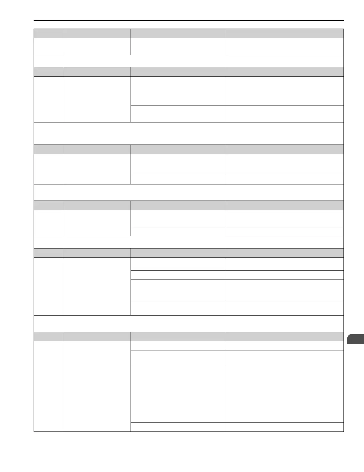
Code Name Causes Possible Solutions
bb Baseblock
An external baseblock command was entered through
one of the MFDI terminals Sx, and the drive output
stopped as shown by an external baseblock command.
Examine the external sequence and timing of the baseblock
command input.
Note:
The drive will not output a minor fault signal for this alarm.
Code Name Causes Possible Solutions
bCE Bluetooth Communication Error
The smartphone or tablet with DriveWizard Mobile is
too far from the keypad.
Move to 10 m (32.8 ft) or less from the keypad.
Note:
bCE can occur when the smartphone or tablet is 10 m (32.8 ft)
or nearer to the keypad for different smartphone and tablet
specifications.
Radio waves from a different device are causing
interference with communications between the
smartphone or tablet and keypad.
Make sure that no device around the keypad uses the same radio
bandwidth (2400 MHz to 2480 MHz), and prevent radio
interference.
Note:
• The drive detects this error when you use a smartphone or tablet and a Bluetooth LCD keypad to operate the drive.
• If the drive detects this error, the terminal set to H2-01 to H2-03 = 10 [MFDO Function Selection = Alarm] will activate.
• Use o2-27 [bCE Detection selection] to enable and disable bCE detection.
Code Name Causes Possible Solutions
BuDif Main Fdbk Lost, Using Diff Fdbk
Parameter Y4-41 = 1 [Diff Lvl Src Fdbk Backup
Select = Enabled] and the drive detected a wire-break
on the analog input terminal set for PID Feedback
[H3-xx = B].
Examine the connection of the Main PID Feedback Transducer.
Main PID Feedback Transducer is broken. Replace Main PID Feedback Transducer.
Note:
• The drive detects this error if it does not receive the PID Feedback signal and it uses Differential Feedback [H3-xx = 2D] as backup.
• If the drive detects this error, the terminal set to H2-01 to H2-03 = 10 [MFDO Function Selection = Alarm] will activate.
Code Name Causes Possible Solutions
Bu-Fb Main Fdbk Lost Using Backup Fdbk
The drive detected wire-break on the analog input
terminal set to H3-xx = B [MFAI Function Selection
= PID Feedback].
Examine the connection of the Main PID Feedback Transducer.
Main PID Feedback Transducer is broken. Replace Main PID Feedback Transducer.
Note:
If the drive detects this error, the terminal set to H2-01 to H2-03 = 10 [MFDO Function Selection = Alarm] will activate.
Code Name Causes Possible Solutions
BuFbl Backup Fdbk Lost Chk/Repl Xducer
The drive detected wire-break on the analog input
terminal set for PID Feedback Backup [H3-xx = 24].
Examine the connection of the Differential PID Feedback
transducer.
Backup PID Feedback Transducer is broken. Replace Backup PID Feedback Transducer.
Parameter Y4-41 = 1 [Diff Lvl Src Fdbk Backup
Select = Enabled] and the drive detected a wire-break
on the analog input terminal set for Differential Level
Source [H3-xx = 2D].
Examine the connection of the Differential PID Feedback
transducer.
Parameter Y4-41 = 1 and the Differential PID
Feedback Transducer is broken.
• Replace the Differential PID Feedback Transducer.
• Set Y4-41 = 0 [Disabled].
Note:
• The drive detects this error if it does not receive the PID Feedback Backup signal.
• If the drive detects this error, the terminal set to H2-01 to H2-03 = 10 [MFDO Function Selection = Alarm] will activate.
Code Name Causes Possible Solutions
bUS Option Communication Error
The communications cable wiring is incorrect. Correct wiring errors.
There is a short-circuit in the communications cable
or the communications cable is not connected.
• Repair short circuits and connect cables.
• Replace the defective communications cable.
Electrical interference caused a communication data
error.
• Examine the control circuit lines, main circuit lines, and ground
wiring, and decrease the effects of electrical interference.
• Make sure that a magnetic contactor is not the source of the
electrical interference, then use a Surge Protective Device if
necessary.
• Use only the recommended cables or other shielded line. Ground
the shield on the controller side or the drive input power side.
• Separate the communication wiring from drive power lines, and
install a noise filter to the input side of the power supply for
communication.
• Decrease the effects of electrical interference from the controller.
The option card is incorrectly installed to the drive. Correctly install the option card to the drive.

 Loading...


