Parameter List
9
9.10 H: Terminal Functions
YASKAWA SIEPYAIH6B01A HV600 AC Drive Bypass Technical Reference 623
Setting Value Function Description Ref.
97 Low Feedback The terminal activates when the drive is in a Low Feedback Condition as specified by Y1-08 [Low Feedback Level]
and Y1-09 [Low Feedback Lvl Fault Dly Time] and when the drive detects an LFB [Low Feedback Sensed] fault or an
LOFB [High Feedback Sensed] alarm.
291
9E Low PI Auxiliary Control
Level
The terminal activates when the PI Aux Feedback Level is less than YF-09 [PI Aux Control Low Level Detect] or if the
drive detects an LOAUX [Low PI Aux Feedback Level] fault.
291
9F High PI Auxiliary Control
Level
The terminal activates when the PI Aux Feedback Level is more than YF-12 [PI Aux Control High Level Detect] or if
the drive detects an HIAUX [High PI Aux Feedback Level] fault.
291
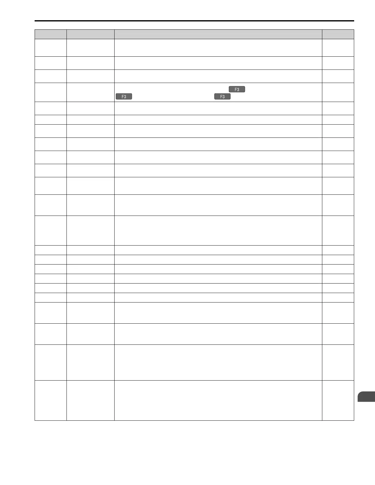
A9 RELAY Operator Control
The terminal changes to OFF or ON when you push the RELAY ( ) button. When the terminal is ON, push
to turn it OFF. When the terminal is OFF, push to turn in ON.
291
AB Thrust Mode The terminal activates when the output frequency is between 0.0 Hz and the value set in Y4-12 [Thrust Frequency] and
the Thrust Bearing function is active.
291
AC Setpoint Not Maintained The terminal activates when the drive detects NMS [Setpoint Not Met] condition. 291
B2 BAS Interlock The terminal activates when the Run command is active or the drive is outputting the voltage. The drive will use this
as an actuation signal for an external damper.
292
B8 Pump Fault The terminal activates when one of these faults is active: LFB [Low Feedback Sensed], HFB [High Feedback Sensed],
NMS [Setpoint Not Met], or EFx [External Fault (Terminal Sx)].
292
B9 Transducer Loss The terminal activates when the current into the analog input associated with PID feedback is more than 21 mA or less
than 3 mA, or an FDBKL [WIRE Break] Fault or an FDBKL [Feedback Loss Wire Break] Alarm is active.
292
BA PI Auxiliary Control
Active
The terminal activates when the PI Auxiliary Controller has an effect on the output speed. 292
BB Differential Feedback
Exceeded
The terminal activates when the difference between the PID Feedback and the value from the terminal set for H3-xx =
2D [Differential Feedback] is more than Y4-18 [Differential Level] for the time set in Y4-19 [Differential Lvl
Detection Time].
292
BC Sleep Active The terminal activates when the Sleep function is active and the drive is not operating.
Note:
The terminal will not activate for Sleep Boost function.
292
BD Start Delay The terminal activates when the Feedback is more than the start level or the Feedback is less than the Inverse PID and
the start timer is timing.
Note:
You must set Y1-04 [Sleep Wake-up Level] ≠ 0 and Y1-05 [Sleep Wake-up Level Delay Time] ≠ 0 to use this
function.
292
BE Pre-Charge The terminal activates when the drive is in Pre-Charge Mode. 292
C0 HAND Mode The terminal activates when the drive is in HAND Mode operation. 292
C1 AUTO Mode The terminal activates when the drive is in AUTO Mode operation. 293
C2 OFF Mode The terminal activates when the drive is in OFF Mode operation. 293
C3 Main Feedback Lost The terminal activates when the drive loses the main PID feedback. 293
C4 Backup Feedback Lost The terminal activates when the drive loses the backup PID feedback. 293
100 !During Run The terminal deactivates when you input a Run command and when the drive is outputting voltage.
ON : Drive is stopping
OFF : Drive is running
293
101 !Zero Speed The terminal deactivates when the output frequency < E1-09 [Minimum Output Frequency].
ON : Output frequency ≥ value of E1-09.
OFF : Output frequency < value of E1-09.
293
102 !Speed Agree 1 The terminal deactivates when the output frequency is in the range of the frequency reference ± L4-02 [Speed Agree
Detection Width].
Note:
The detection function operates in the two motor rotation directions.
ON : The output frequency does not align with the frequency reference although the drive is running.
OFF : The output frequency is in the range of “frequency reference ± L4-02”.
293
103 !User-Set Speed Agree 1 The terminal deactivates when the output frequency is in the range of L4-01 [Speed Agree Detection Level] ± L4-02
[Speed Agree Detection Width] and in the range of the frequency reference ± L4-02.
Note:
The detection function operates in the two motor rotation directions. The drive uses the L4-01 value as the
forward/reverse detection level.
ON : The output frequency is not in the range of “L4-01 ± L4-02” or the range of frequency reference ± L4-02.
OFF : The output frequency is in the range of “L4-01 ± L4-02” and the range of frequency reference ± L4-02.
293

 Loading...


