Network Communications
10
10.5 Metasys N2 Communications
YASKAWA SIEPYAIH6B01A HV600 AC Drive Bypass Technical Reference 729
■ Connect Communications Cable
Use this procedure to start communication between the controller and bypass.
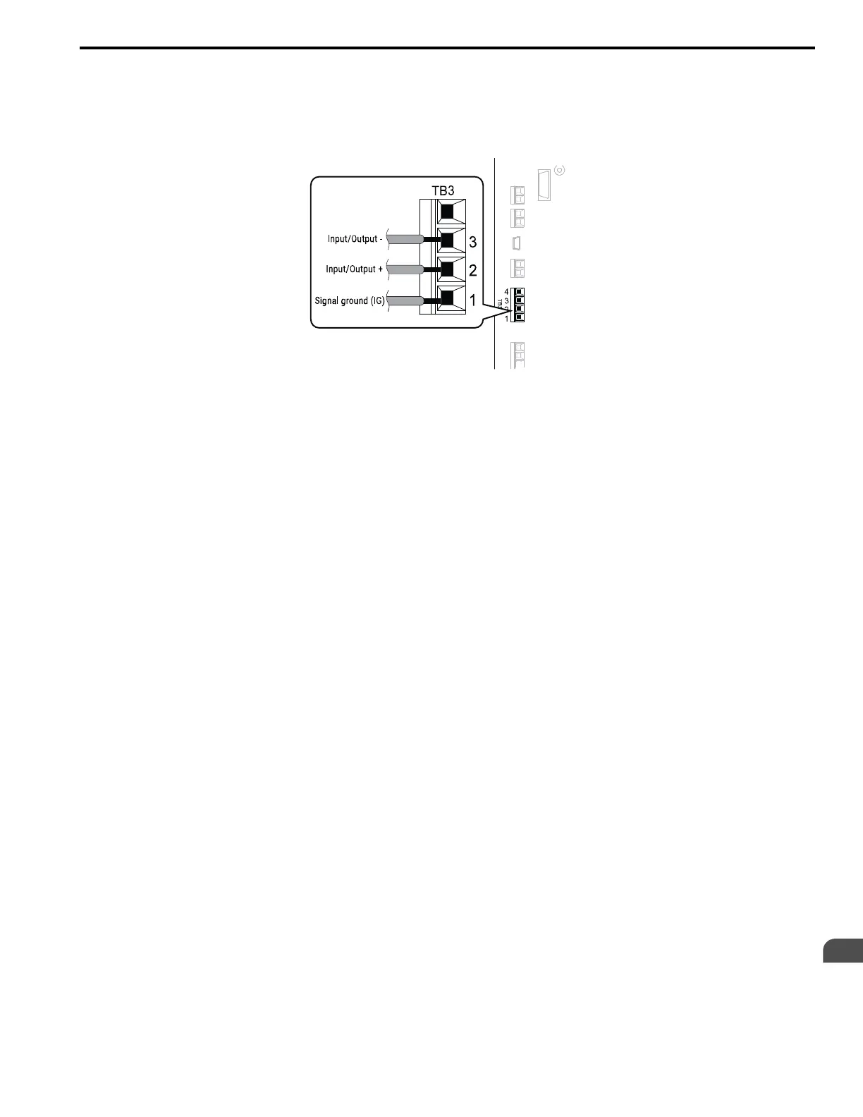
1. De-energize the bypass then connect the communications cable to the controller and the bypass. The bypass
uses terminal TB3 for serial communications.
Figure 10.11 Communications Cable Connection Terminal (TB3)
Note:
Isolate the communications wiring from the main circuit wiring and other high-power wiring. Use shielded wires for the
communications wiring and connect cable sheaths as shown in “Wiring Diagram for More than One Bypass”. Incorrect wiring
procedures could cause bypass malfunction because of electrical interference.
2. Enable the termination resistor ONLY when the bypass is at the end of the communications network. Set DIP
switch S1 to the “ON” position to enable the termination resistor. Refer to “Set the Termination Resistor” for
more information.
3. Energize the bypass.
4. Use the keypad to set the necessary communications parameters H5-01 to H5-12.
• H5-01 [Drive Node Address]
• H5-02 [Communication Speed Selection]
• H5-04 [Stopping Method after Com Error]
• H5-05 [Comm Fault Detection Select]
• H5-08 [Communication Protocol Selection]
• H5-09 [CE Detection Time]
5. Because communications parameters do not take effect immediately, either de-energize and re-energize the
bypass or set H5-20 = 1 [Communication Parameters Reload = Reload Now].
The bypass is prepared to start communication with the controller.
■ Set the Termination Resistor
You must enable the termination resistor on the serial terminals of the bypasses on the two physical ends of the
network to use serial communications. Use DIP switch S1 on the bypass control PCB to enable and disable the built-
in termination resistor. Refer to Figure 10.12 for an example of how to set DIP switch S1. Use the tip of a tweezers or
a small flat-blade screwdriver to set the DIP switch. When you install the bypass at the end of the network line, set
DIP switch S1 to “ON” to enable the termination resistor. Set DIP switch S1 to “OFF” on all other bypasses.
 Loading...


