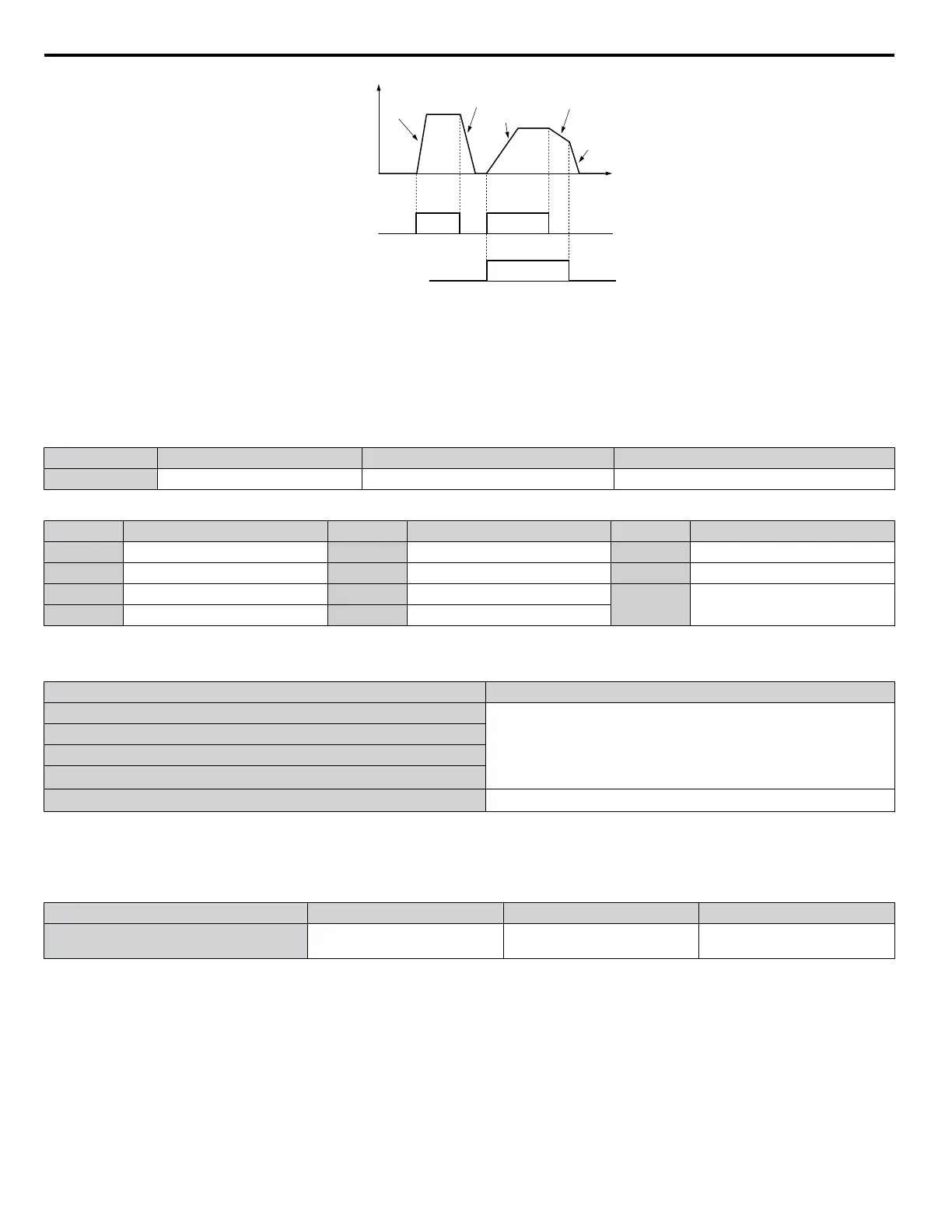
Output
frequency
Accel Time 1
(C1-01)
Decel Time 1
(C1-02)
Accel Time 2
(C1-03)
Decel Time 2
(C1-04)
Decel Time 1
(C1-02)
Time
FWD (REV)
Run command
ON
OFF
ON
ON
Accel/Decel Time Selection 1
(Terminals S1 to S8, H1-oo = “7”)
OFF
Figure 4.16 Timing Diagram of Accel/Decel Time Change
n
C6-02: Carrier Frequency Selection
Sets the switching frequency of the drive output transistors. Changes to the switching frequency lower audible noise and reduce
leakage current.
Note: Increasing the carrier frequency above the default value automatically lowers the drive current rating.
No. Parameter Name Setting Range Default
C6-02 Carrier Frequency Selection 1 to F 7
Settings:
C6-02 Carrier Frequency C6-02 Carrier Frequency C6-02 Carrier Frequency
1 2.0 kHz 5 12.5 kHz 9 Swing PWM 3
2 5.0 kHz 6 15.0 kHz A Swing PWM 4
3 8.0 kHz 7 Swing PWM 1
F User defined (C6-03 to C6-05)
4 10.0 kHz 8 Swing PWM 2
Note: Swing PWM uses a carrier frequency of 2.0 kHz as a base, then applies a special PWM pattern to reduce the audible noise.
Guidelines for Carrier Frequency Parameter Setup
Symptom Remedy
Speed and torque are unstable at low speeds
Lower the carrier frequency.
Noise from the drive affects peripheral devices
Excessive leakage current from the drive
Wiring between the drive and motor is too long
<1>
Audible motor noise is too loud
Increase the carrier frequency or use Swing PWM.
<2>
<1> The carrier frequency may need to be lowered if the motor cable is too long. Refer to Table 4.12.
<2> The default carrier frequency is Swing PWM (C6-02 = 7), using a 2 kHz base. Increasing the carrier frequency is permissible , however the drive
rated current is reduced when the carrier frequency is increased.
Table 4.12 Wiring Distance and Carrier Frequency
Wiring Distance Up to 50 m Up to 100 m Greater than 100 m
Recommended setting value for C6-02 1 to F (up to 15 kHz)
1 to 2 (up to 5 kHz),
7 (Swing PWM)
1 (up to 2 kHz), 7 (Swing PWM)
n
d1-01 to d1-17: Frequency Reference 1 to 16 and Jog Frequency Reference
The drive lets the user switch between up to 17 preset frequency references during run (including the Jog reference) through
the digital input terminals. The drive uses the acceleration and deceleration times that have been selected when switching
between each frequency reference.
The Jog frequency overrides all other frequency references and must be selected by a separate digital input.
The multi-speed references 1, 2, and 3 can be provided by analog inputs.
4.6 Basic Drive Setup Adjustments
100
YASKAWA ELECTRIC TOEP YAIP1U 01B YASKAWA AC Drive - P1000 Quick Start Guide