n
H4-02, H4-03: Multi-Function Analog Output Terminal FM Gain and Bias
H4-05, H4-06: Multi-Function Analog Output Terminal AM Gain and Bias
Parameters H4-02 and H4-05 set the terminal FM and AM output signal level when the value of the selected monitor is at
100%. Parameters H4-03 and H4-06 set the terminal FM and AM output signal level when the value of the selected monitor
is at 0%. Both are set as a percentage, where 100% equals 10 Vdc or 20 mA analog output and 0% equals 0 V or 4 mA. The
output voltage of both terminals is limited to +/-10 Vdc.
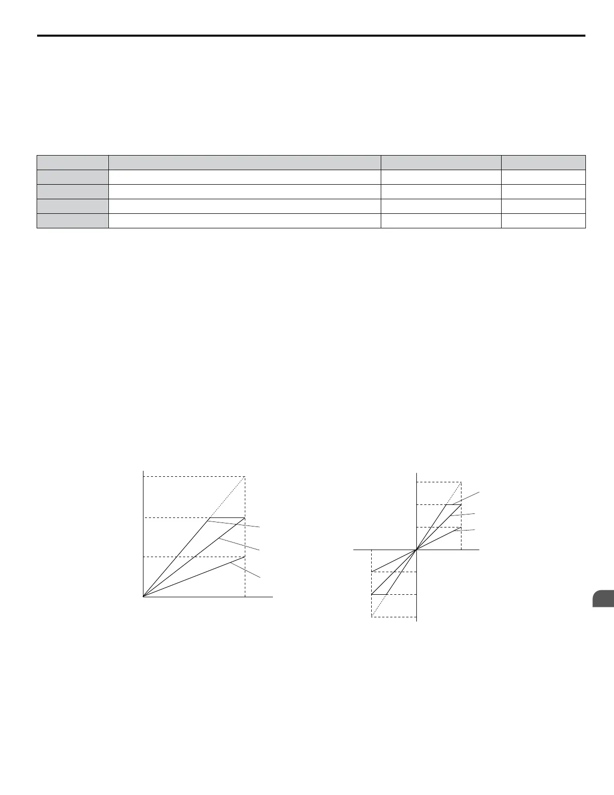
The output signal range can be selected between 0 to +10 Vdc or -10 to +10 Vdc, or 4 to 20 mA using parameter H4-07 and
H4-08. Figure 4.25 illustrates how gain and bias settings work.
No. Name Setting Range Default
H4-02 Multi-Function Analog Output Terminal FM Gain -999.9 to 999.9% 100.0%
H4-03 Multi-Function Analog Output Terminal FM Bias -999.9 to 999.9% 0.0%
H4-05 Multi-Function Analog Output Terminal AM Gain -999.9 to 999.9% 50.0%
H4-06 Multi-Function Analog Output Terminal AM Bias -999.9 to 999.9% 0.0%
Using Gain and Bias to Adjust Output Signal Level
The output signal is adjustable while the drive is stopped.
Terminal FM
1.
View the value set to H4-02 (Terminal FM Monitor Gain) on the digital operator. A voltage equal to 100% of the
parameter being set in H4-01 will be output from terminal FM.
2.
Adjust H4-02 viewing the monitor connected to the terminal FM.
3.
View the value set to H4-03 on the digital operator; terminal FM will output a voltage equal to 0% of the parameter
being set in H4-01.
4.
Adjust H4-03 viewing the output signal on the terminal FM.
Terminal AM
1.
View the value set to H4-05 (Terminal AM Monitor Gain) on the digital operator. A voltage equal to 100% of the
parameter being set in H4-04 will be output from terminal AM.
2.
Adjust H4-05 viewing the monitor connected to the terminal AM.
3.
View the value set to H4-06 on the digital operator; terminal AM will output a voltage equal to 0% of the parameter
being set in H4-04.
4.
Adjust H4-06 viewing the output signal on the terminal AM.
Output Voltage
Output Voltage
0 V
5 V
10 V
Gain 150%
Bias 0%
Gain = 150%
Bias = 0%
Gain = 100%
Bias = 0%
Gain = 50%
Bias = 0%
Gain 100%
Bias 0%
Gain 50%
Bias 0%
100%
Monitor Value
Monitor Value
0%
H4-07, 08 = 0 H4-07, 08 = 1
10 V
-10 V
100%
5 V
15 V
-5 V
-15 V
-100%
Figure 4.25 Analog Output Gain and Bias Setting Example 1 and 2
Set H4-03 to 30% for an output signal of 3 V at terminal FM when the monitored value is at 0%.
4.6 Basic Drive Setup Adjustments
YASKAWA ELECTRIC TOEP YAIP1U 01B YASKAWA AC Drive - P1000 Quick Start Guide
113
4
Start-Up Programming &
Operation

 Loading...


