2-1
IM80B80T10E 21th Edition : Jul.1,2007-00
< 2.OVERVIEW >
2. OVERVIEW
2.1 General
The EML 500 series of electromagnetic logs successfully meets the performance requirements
prescribed by IMO resolution A478 (XII), and has been approved by the Ministry of Land,Infrastructure
and Transport Japan (approval no.:3795).
The EML500 features:
(1) Versatile external interfaces
· Pulse output (photocoupler / contact)
· Digital output (NMEA0183)
· Analog speed output (0V DC to 5V DC)
· Alarm contact and interface with the GPS
(2) High reliability
The use of highly integrated circuits, such as microprocessors, provides excellent reliability due to
a reduction in parts and the elimination of moving parts.
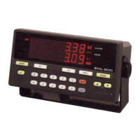
(3) Master indicator for displaying the speed and distance
(4) Variety of sensors available to meet various installation requirements.
A dual-axis sensor can measure not only the longitudinal speed, but also the transverse speed.
(5) Built-in self-diagnostic function
2.2 Principle
The principle of electromagnetic logs is based on Faraday’s law of electromagnetic induction.
An electromotive force is induced in a conductor whenever there is relative motion between the
conductor and magnetic field.
The directions of the magnetic field, motion and induced emf are at right angles or perpendicular to
each other.
If the magnetic field is fixed, the magnitude of the induced emf is proportional to the speed of the
motion (see Figure ”Principle”).
Therefore, either the conductor or magnetic field must move to induce an electromotive force.
In the case of electromagnetic logs, the magnetic field moves along with the ship while the seawa-
ter (the conductor) remains stationary.
There is a coil in the sensor at the top of the measurement rod, and this coil is energized to establish
a magnetic field around the sensor. As the ship moves, an emf is induced which is then detected
by a pair of electrodes at the tip of the sensor (see Figure “Flattened Sensor Structure”).
 Loading...


