2-2
IM80B80T10E 21th Edition : Jul.1,2007-00
< 2.OVERVIEW >
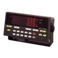
Magnetic flux
Electromotive
force
Direction of
induced emf
Direction of
magnetic field lines
Direction of motion
Figure Principle
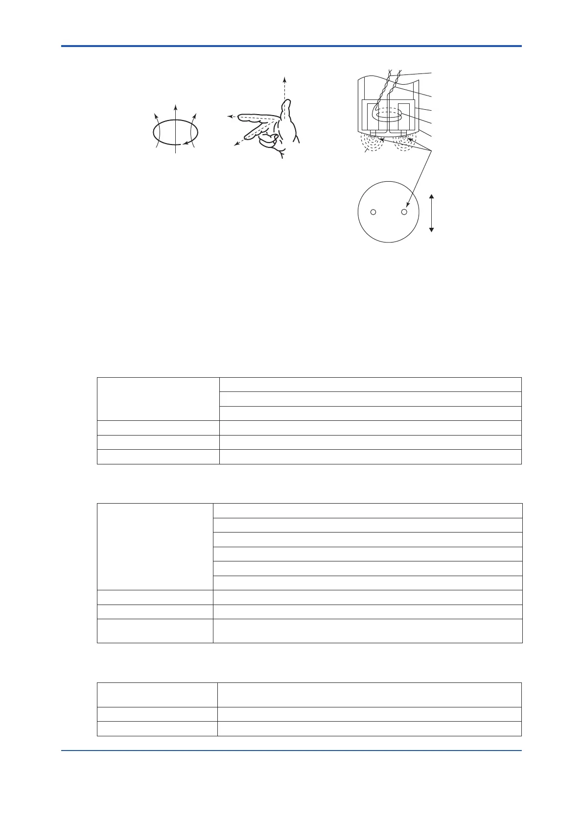
Exciting current
Induced voltage
Iron core
Coil
Rod
Electrodes
Direction of moving ship
Magnetic flux
Figure Flattened Sensor Structure
Here an induced emf can be obtained from the for-
mula below.
e = B·V·D·10
-4
Volt
where
B = Flux density (Tesla)
V = Speed (cm/s)
D = Distance between electrodes (cm)
2.3 PerformanceandSpecications
(1) Power supply
Power supply voltage: 100 / 110 / 115 V AC ±10 % (50 / 60 Hz ±6 %)
200 / 220 V AC ±10 % (50 /60 Hz ±6 %)
(can be selected by changing the jumper setting in the power supply unit.)
Power consumption: 80 VA
Insulation resistance: at least 10MΩ using 500V megger (excluding electronic circuits)
Withstanding voltage: 1500 V AC for 1 min (excluding electronic circuits)
(2) Measuring Range
Speed:
(*1: Additional engineering is
required concerning the in-
stallation of the sensor.)
-4 kt to 20 kt.
-5kt to 25 kt.
-8 kt to 40 kt.
-7 kt to 35 kt.
-10 kt to 50 kt. (*1)
-13 kt to 65 kt. (*1)
Transverse speed: 0 kt to ± 6.5 kt.
Distance: 0 nm to 9999.99 nm
Direction of ship movement: 0 to 359 deg., clockwise from the bow-to-stern line
(xed to 0 deg if the resultant speed is 0.5 kt or less)
(3) Measuring Accuracy
Speed: ± 0.15 kt. with respect to standard signal inputs
(± 0.25 kt. or less if the measuring range is above 40 kt.)
Distance: ± 0.05 nm/h or ± 1.0% max., whichever is larger
Direction of ship movement: deg max = ±2.5 deg
 Loading...


