EasyManuals Logo

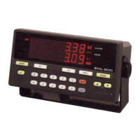
YOKOGAWA EML500 Series User Manual

YOKOGAWA EML500 Series
85 pages
To Next Page IconTo Next Page
To Previous Page IconTo Previous Page
Page #71 background imageLoading...
Page #71 background image
A-2
IM80B80T10E 21th Edition : Jul.1,2007-00
< Appendix >
Appendix 2 : Master Unit Block Diagram
9
10
29
30
19
20
7
8
27
28
17
18
23
24
25
24
25
26
21
22
23
26
1
2
11
12
1
2
11
12
7
8
9
10
27
28
29
30
3
4
5
6
13
14
15
16
3
4
5
6
13
14
15
16
9
1
2
10
13
14
15
1
2
3
6
7
8
4
5
11
12
2P
2P
2P
4P
4P
V/I CONV.
V/I CONV.
V/I CONV.
V/I CONV.
NMEA0183 DRIVER
RELAY
PHOTO COUPLER
BUFFER BUFFER BUFFER BUFFER
RAMROM
CPU
WDT
RST
SIO
SIO
PIO
PIO
I/O DECORDER
MPX
CTC
M.
I/O
I/O
1
2 3 4 5 6 1 2 3 4 5
6 1 2 3 4 5 6 1 2 3 4 5 6
FILTER
OPTION
TB4
DC24V
AGND
+5V +15V
−15V
J12 J22 J21 J11
DECODER
DECODER
1 Chip CPU
DATA BUS
ADRS BUS
BUFFER
LATCH
DRIVER
+15V
DIG.SW DIP.SW
I/V CONV.
I/V CONV.
1
2
3
4
5
TB1
TB3
TB3
TB1
TB1
TB1
TB1
TB3
TB3
TB2
Sample hold
Sample hold
Sample hold
Sample hold
D/A CONVERTER
reference
voltage
5V
SWITCHING POWER SUPPLY SWITCHING POWER SUPPLY
Current output for
analog speed
0mA to 20mA
4ch
Voltage output for
analog speed
0V to 5V
2ch
indicator output
2ch
indicator input
1ch
NMEA0183 output
2ch
NMEA0183 input
1ch
Current output for
speed (relay) 2ch
Limit contact output
for speed (relay) 2ch
Alarm contact output
for speed (relay) 2ch
Sensor signal input
(X / Y direction)
Contact output for
speed (
photo coupler
)
4×2 ch
24V POWER SUPPLY
From sensor
From master indicator
From speed indicator
±15V POWER SUPPLY
SYSTEM POWER SUPPLY
(100V to 220V)
COMPARATOR
+15V
–15V

Table of Contents

Questions and Answers:

Question and Answer IconNeed help?

Do you have a question about the YOKOGAWA EML500 Series and is the answer not in the manual?

YOKOGAWA EML500 Series Specifications

General IconGeneral
BrandYOKOGAWA
ModelEML500 Series
CategoryMeasuring Instruments
LanguageEnglish

Related product manuals