6-24
IM80B80T10E 21th Edition : Jul.1,2007-00
< 6.INSTALLATION >
6.9 Maintenance Functions
6.9.1
Intermediate Error Compensation Factor
(
Maintenance Mode
)
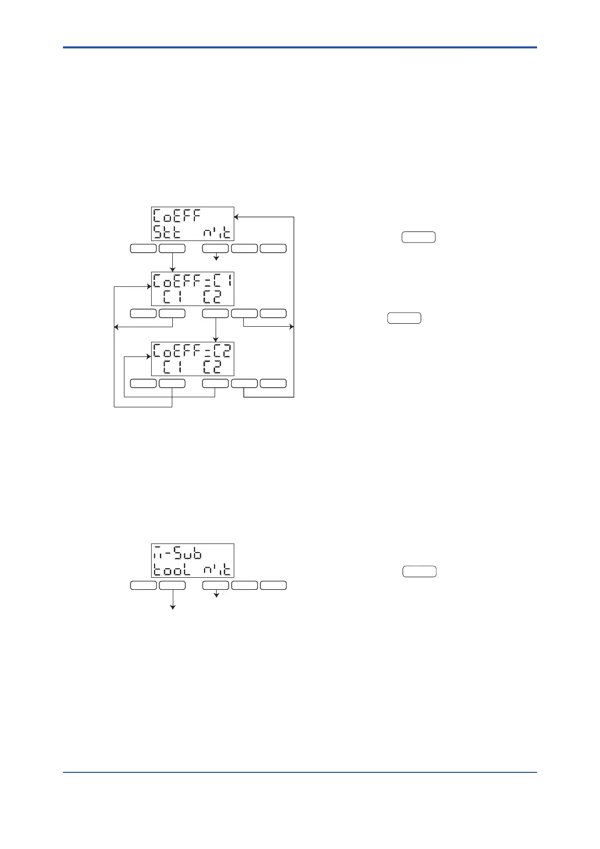
Two linearizer tables are available for intermediate error compensation, and either can be selected
in this mode. Therefore, compensation based on the newest linearizer table of compensation based
on the previous linearizer table can be done selectively if the compensation coefcient is changed
alternately each time milepost measurement is done.
The selective use of these linearizer tables is also useful for ships whose speeds differ when they
are fully loaded.
The operation procedure is shown below.
At -5-8, press the
key to enter the mode
for selecting a coefcient. The display then chang-
es to that marked a.
At a, the display indicates that coefcient 1 (C1) is
currently selected. To select coefcient 2 (C2) in-
stead, press the
key while the display is at
a. The display then change to that marked b where
coefcient 2 (C2) is selected.
6.9.2 Sub-maintenance Mode
Select the sub-maintenance mode to perform the switch status display, voltage check, xed voltage
output, or GPS interface setting .
The operation procedure is shown below.
This is the entrance to the sub-maintenance
mode.
At -5-9, press the
key to select the sub-
maintenance mode. The display then advances to
-5-A1.
F 1 F 2
DISPL
PREV
MODE
F 1 F 2
DISPL
PREV
MODE
MAINT
MAINT
F 1 F 2
DISPL
PREV
MODE
MAINT
a.
b.
-5-8
-5-9
-5-81
F 1 F 2
DISPL
PREV
MODE
F 1 F 2
DISPL
PREV
MODE
MAINT
MAINT
F 1 F 2
DISPL
PREV
MODE
MAINT
a.
b.
-5-8
-5-9
-5-81
F 1 F 2
DISPL
PREV
MODE
MAINT
a.
-5-9
-5-1
-5-A1
F 1 F 2
DISPL
PREV
MODE
MAINT
a.
-5-9
-5-1
-5-A1
 Loading...


