4-2
IM80B80T10E 21th Edition : Jul.1,2007-00
< 4.OPERATION >
4.2 Functions of Master Indicator Components
The functions of the switches and keys on the master indicator are summarized below.
Switch / key Function
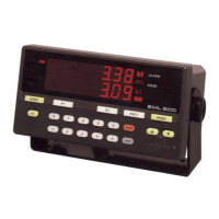
Switching of data items on the display
Speed
Total distance
traveled
Trip distance
“RESET”
Longitudinal speed and
Transverse speed
Resultant
speed
Direction
The items on the display switch to the next items each time the DISPL key is pressed.
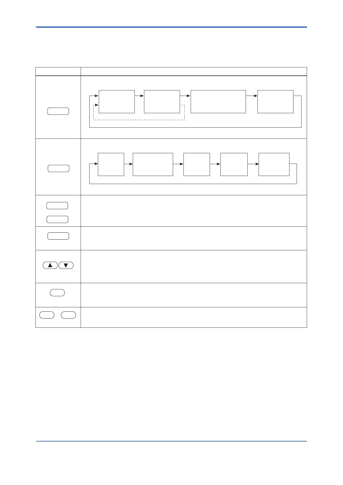
Switching of operation mode
Alarm
Setting
Test
Function
Input signal
Selection
(log / GPS)
(Adjustment)
Error Code
Display
The operation mode switches to the next one each time the MODE key is pressed.
A function displayed on the bottom line of the display can be selected by pressing either the F1 or F2
key.
Pressing this key moves the operation sequence one step back.
These keys control the intensity of the light as follows:
▲ Brighter
▼ Dimmer
Pressing this key starts the lamp test by turning on all lamps.
Press this key again to return to the state immediately before the lamp test.
to
These are used for entering data.
 Loading...


