5-6
IM80B80T10E 21th Edition : Jul.1,2007-00
< 5.MAINTENANCE>
5.5 Inspection of the Measurement Rod
CAUTION
Do not use a megger for inspection purposes except for on-board power supply terminals. Other-
wise, the equipment may be damaged.
Remove the measurement rod from the sewater valve.
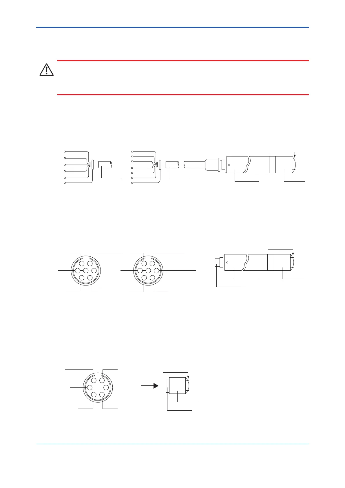
(1) Cable, Rod Case, and Sensor
F
A
B
E
C
D
E
F
A
E
C
D
E
Rod case
CableCable
Sensor
Electrodes
24V
Sensor output (Y)
Sensor output (X)
0V
+15V
-15V
SHIELD
24V
Sensor output
0V
+15V
-15V
SHIELD
Single - indication
(HS1 / HD1 / HV1/ FA1 / RD1)
Dual - indication
(HV2 / FA2)
(2) Rod Case and Sensor
Cross-section of Connector
B
C
D
E
F
A
G
B
C
D
E
F
A
G
Sensor output
+15V
-15V
0V
24V
Sensor output
(longitudinal)
Sensor output
(transverse)
+15V
-15V
0V
24V
Connector
Rod case
Sensor
Electrodes
Single - indication
(HS1 / HD1 / HV1 / FA1 / RD1)
Dual - indication
(HV2 / FA2)
(3) Sensor
The connector on the sensor has the same pin arrangement as the connector at the end of the rod.
Cross-section of Connector (HD1, RS1, RD1)
Sensor output
+15V -15V
0V
24V
Connector
Sensor
Electrodes
(Viewed from the direction of the arrow)
 Loading...


