3-5
IM80B80T10E 21th Edition : Jul.1,2007-00
< 3.COMPONENTS >
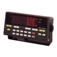
3.3.2 Junction box : LN052
This is a repeater junction box placed between the sensor and master unit. This allows the cable
supplied to the shipbuilder to be connected to the EML500 cable.
Figure Junction box (LN052)
3.3.3 Master Unit : LT501
Supplies the power (24 V and ±15 V) to the amplier in the sensor ,and receives speed data signals
from the sensor. After adjusting the data, the master unit then transmits the speed and distance to
external devices in various signal forms. For operation of the master unit , refer to Section 1.2 in
Chapter 1 and Sections 4.1 in Chapter 4.
Figure Master Unit (LT501)
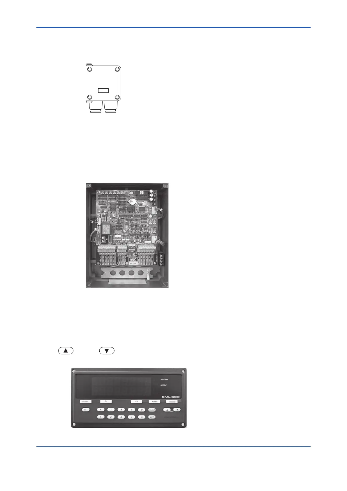
3.3.4 Master Indicator : LR523
Receives digital signals from the master unit, and displays the speed and distance. Both the display
and operation panel are on the front of the master indicator. Set data are sent to the master unit in
the form of digital signals, and placed in the memory. The LED display allows speed and distance
data to be read clearly even in direct sunlight. The dimmer keys control the intensity of the light (
-brighter; -dimmer). For details, refer to Chapter 4.
Figure Master Indicator (LR523)
 Loading...


