5-7
IM80B80T10E 21th Edition : Jul.1,2007-00
< 5.MAINTENANCE >
Continuity check
NOTE
Use a digital multimeter for a continuity check.
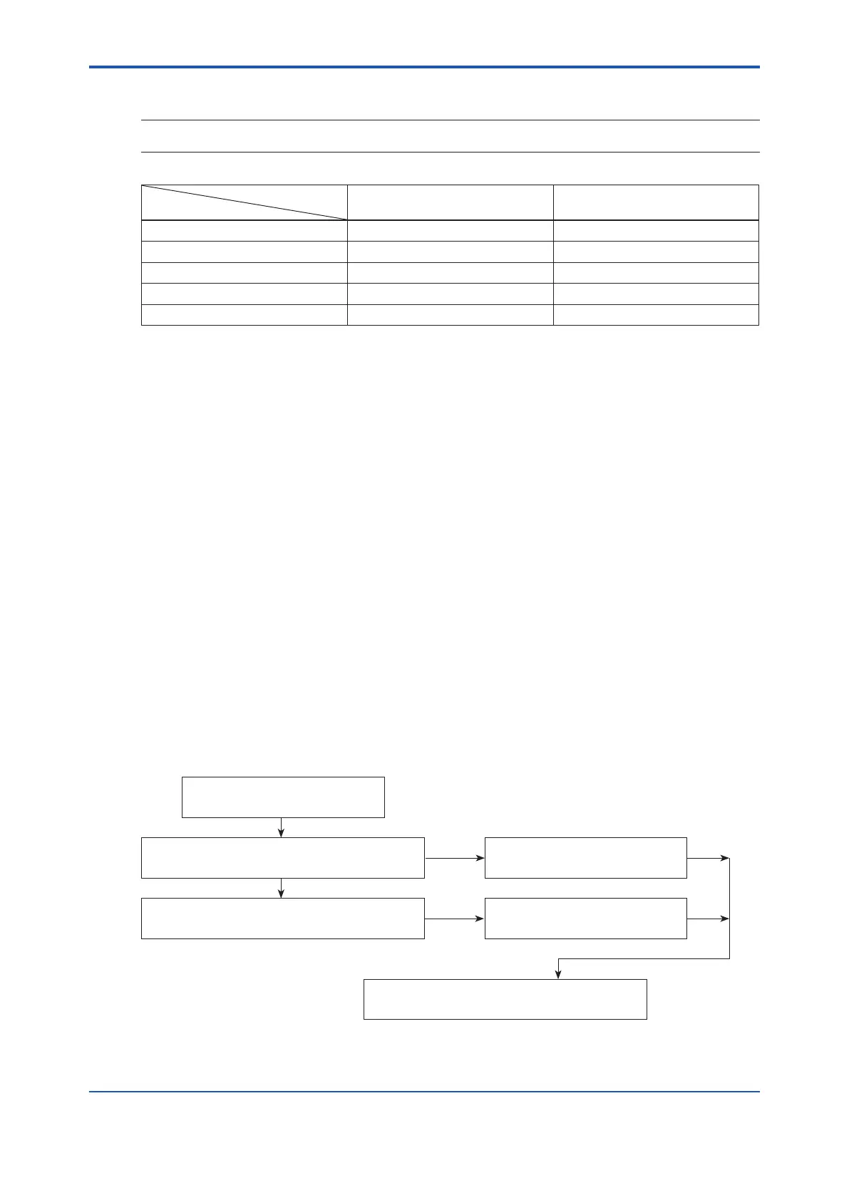
Tester Polarity
Terminals
G, E : NEGATIVE G, E : POSITIVE
E-A (0V - sensor output) O.L O.L
E-B (*1) O.L O.L
E-C (0V - +15V) 6kΩ min 6 kΩ min
E-D (0V- -15V) 1.2MΩ min 10MΩ min
E-F (0V - 24V) 5MΩ min 3MΩ min
*1: For dual-indication model only
Between the electrode and rod case (on the right) : MΩ min = 1MΩ
Between the electrode and rod case (on the left) : MΩ min = 1MΩ
Between G and rod case (metal part of the sensor) : 0Ω
For dual-axis sensor.
Between the electrode and case (longitudinally) : MΩ min = 1MΩ
Between the electrode and rod case (transversely) : MΩ min = 1MΩ
The purpose of this check is for conrmation if sea water entered (or did not enter) in Sensor.
Though the measured data should be a little different by makers and kinds of tester,
If the data is over 6Ω, there will be no problem.
Concerning the operating check of Sensor Checker (Extra-sold: QY001) should be used.
5.6 Inspection of the Seawater Valve
check of the seawater valve
Before replacing the measurement rod, check the
valve handle. Does the handle work smoothly?
Slightly loosen the nut (
in Figure “Sensor
Installation”). Does the handle work smoothly?
Upon completion of the replacement.
Tighten the nut as it was before.
Replace the measurement rod.
Replace the measurement rod.
YES
NO
YES
 Loading...


