1-2
IM80B80T10E 21th Edition : Jul.1,2007-00
< 1.INTRODUCTION >
(2) Master Unit
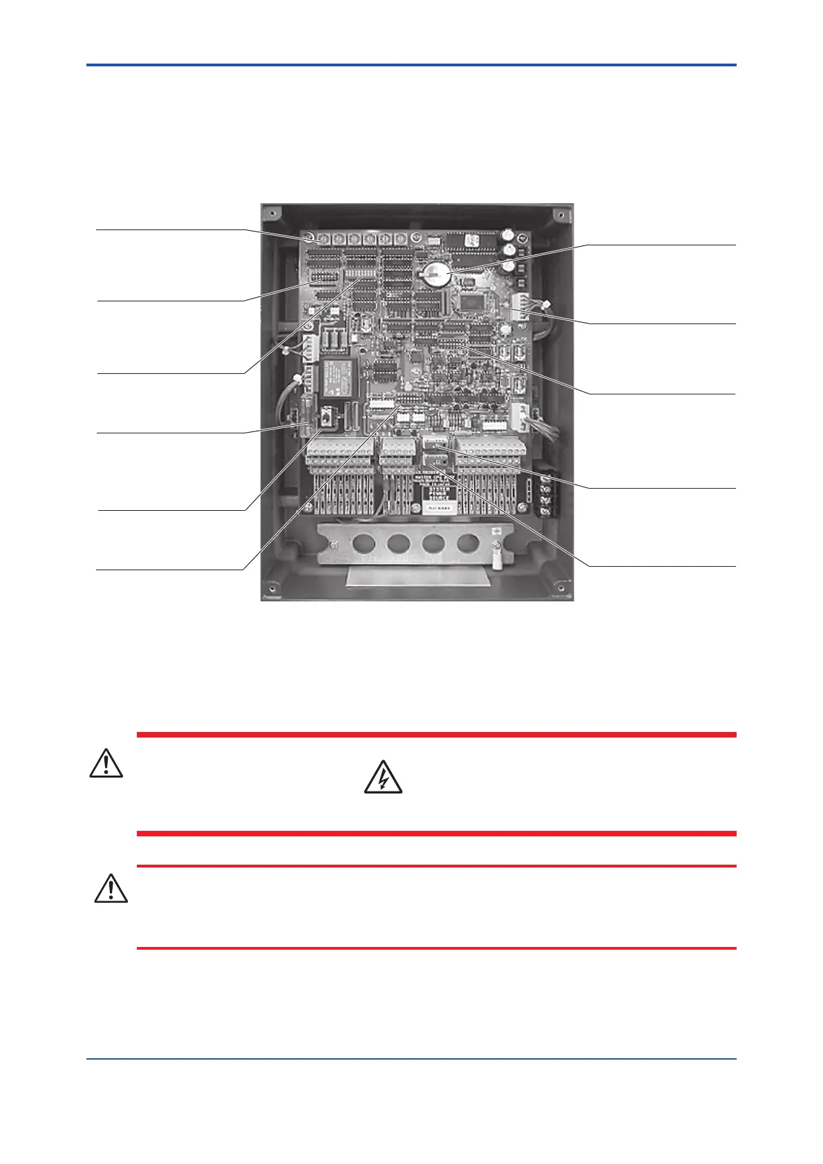
The operation panel on the master unit is shown below, with its cover removed.
SW2 to SW7
: digital switches
(for maintenance setting)
SW8 : dip switch
(for system and
maintenance setting)
MDS1
:
error indication LED unit
FU1 :
fuse for the main power
5A for 24V DC
2A for 100 to 220V AC
SW1 : power supply switch
(for supplying power to the
entire system)
SW11 : dip switch
(for switching the current
output)
BT1 :
memory backup battery
Power LED
SW9 : dip switch
(for switching the relay
contact; NC or NO)
FU4 : 2A fuse
(for the speed indicator)
FU3 : optional furse of 1A
(for the speed indicator)
WARNING
Electrical shock
To avoid electrical shock, turn off the power before making wiring connections.
CAUTION
Do not use a megger for inspection purposes except for on-board power supply terminals.
Otherwise, the equipment may be damaged.
 Loading...


