2-2
<Toc> < 2. Initial Settings >
IM 05D01C02-41E 3rd Edition: May 31, 2006-00
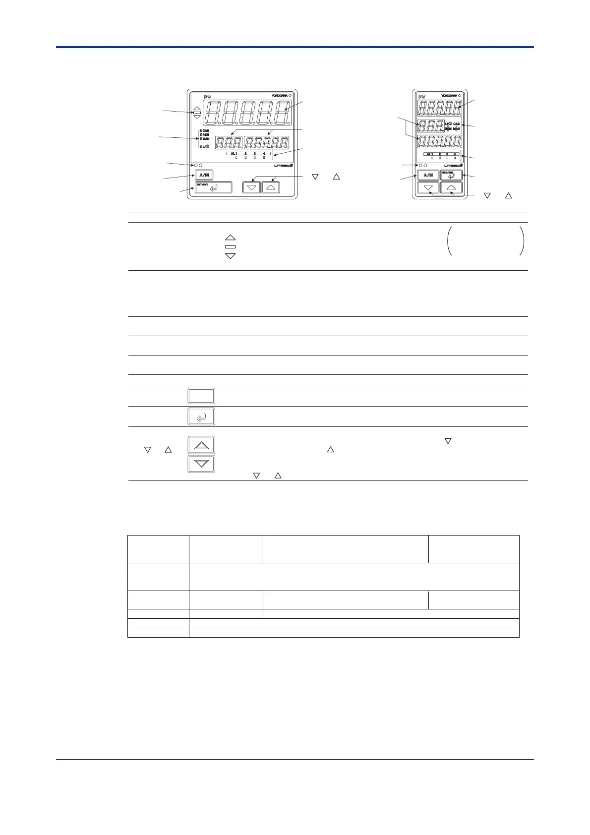
2.1 Names and Functions of Front Panel Parts
Name of Part
Function
1.
Deviation monitor
(for UT550 only)
2.
Status indicator
lamps
3. Light-loader interface
4.
Process variable (PV)
display
5. Setpoint display
6. Alarm indicator lamps
6. Alarm indicator
lamps
2. Status
indicator lamps
3. Light-loader
interface
7. A/M key
8. SET/ENT
key
4. Process
variable (PV)
display
5. Setpoint
display
4. Process
variable (PV)
display
5. Setpoint
display
1. Deviation
monitor
6. Alarm
indicator
lamps
2. Status indicator
lamps
3. Light-loader
interface
7. A/M key
8. SET/ENT key
7.
A/M key
Used to switch between the AUTO and MAN modes. Each time you press the key, it switches to the
AUTO or MAN mode alternately.
8.
SET/ENT
key
SET/ENT
Used to switch or register a parameter. Pressing the key for more than 3 seconds allows you to switch
between the operating display and the main menu for operating parameter setting display alternately.
9.
Used to change numerical values. On setting displays for various parameters, you can change target
setpoints, parameters, and output values (in manual operation). Pressing the key decreases a
numerical value, while pressing the key causes it to increase. You can hold down a key to gradually
increase the speed of change. To change from the parameter setting (operating or setup) display to the
menu or from the setup parameter setting display menu to operating parameter setting display menu,
press the and keys simultaneously.
A/M
When lit, indicates the status of a deviation (PV - SP).
: Is lit (in orange) if a deviation exceeds the deviation display range.
: Is lit (in green) when a deviation is within the deviation display range.
: Is lit (in orange) if a deviation falls below the deviation display range.
The deviation monitor goes off if any display other than the operating display or SELECT display is shown.
Is lit (in green) to indicate the status of operation or control.
CAS: Not used in Single-loop Control.
REM: Is lit when in remote mode.
MAN: Is lit when in manual mode.
LP2: Not used in Single-loop Control.
Interface for an adapter cable used when setting and storing parameters from a PC.
This requires an optional parameter setting tool.
Displays PV.
Displays an error code (in red) if an error occurs.
Displays a parameter symbol in 3-digit LED.
Displays the setpoint of a parameter in 5-digit LED.
If any of alarms 1 to 4 occurs, the respective alarm indicator lamp (AL1 to AL4) is lit (in orange).
9. and keys
9. and keys
and
keys
The deviation display
range can be changed
using the setup
parameter “DVB”.
■ Setting of Main Parameters at the Factory before Shipment
Factory-shipped values
for standard type
controllers
Factory-shipped values
for heating/cooling type controllers
Factory-shipped values for
position proportional type
controllers
Remote input signal
(only for controllers
with remote inputs)
Control output
Relay output (fixed)
Control action Reverse action (variable) Not specified
PID parameter P = 5.0%, I = 240 seconds, D = 60 seconds.
Alarm output
Item
1 to 5 V DC (variable)
Alarm-1: PV high limit, Alarm-2: PV low limit, Alarm-3: PV high limit, Alarm-4: PV low limit
Time proportional PID
relay output (variable)
Heating side: Time proportional PID relay output (variable)
Cooling side: Time proportional PID relay output (variable)

 Loading...


