3-8
<Toc> < 3. Operations >
IM 05D01C02-41E 3rd Edition: May 31, 2006-00
3.7 Switching between Run and Stop
Selection between the Run state (RUN) and Stop state (STOP) can be made with contact
input 2 (DI2). (Factory-set default)
“RUN” when DI2 is set to OFF
18
20
“STOP” when DI2 is set to ON
18
20
SET/ENT
A/M
PV
AL1234
REM
CAS
MAN
LP2
When the controller is stopped, input and outputs are as follows:
PV input Displays the PV value.
Control output
Alarm output Turns the output on in case of an alarm.
Provides the preset output value
(factory-set to 0%).
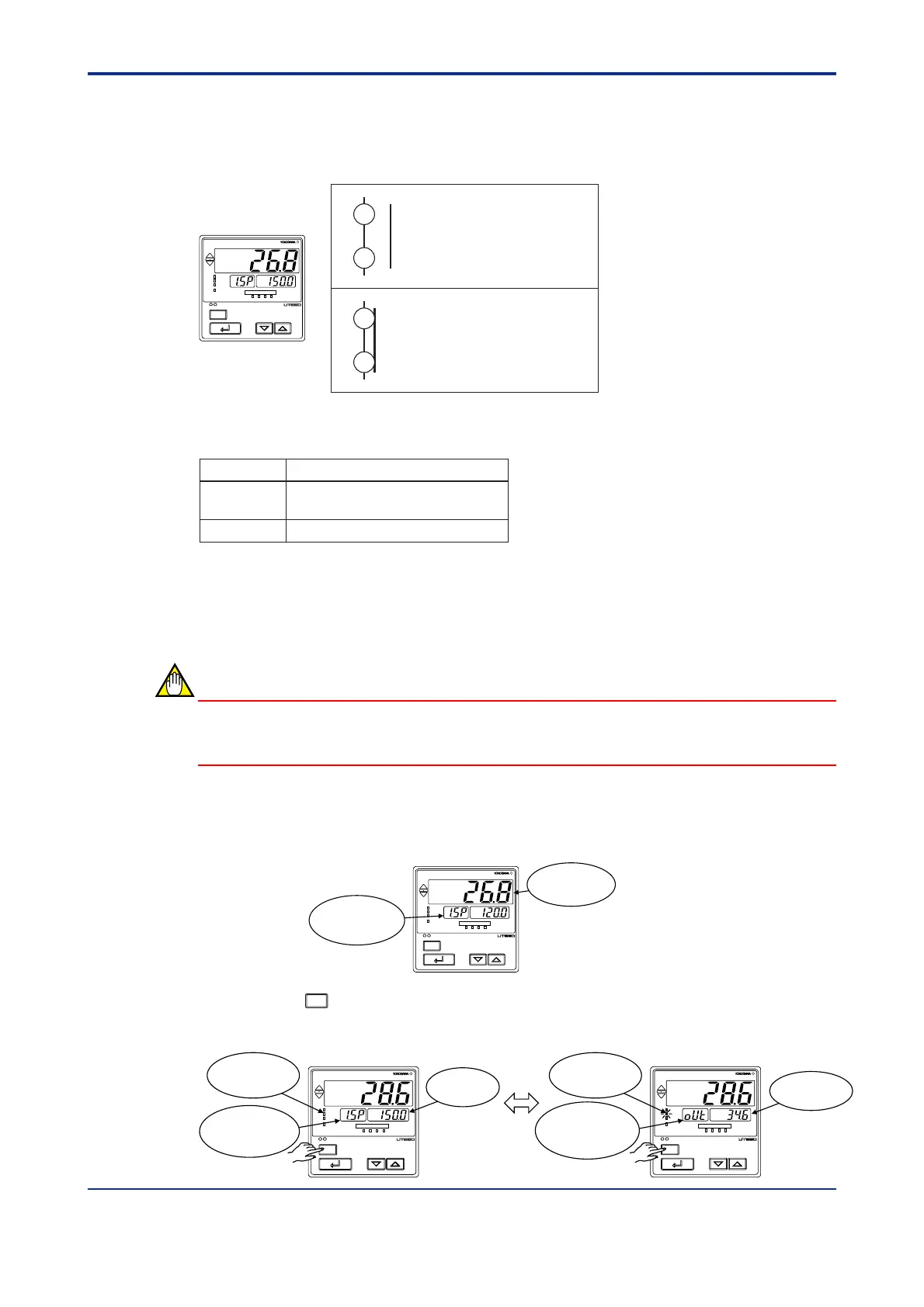
3.8 Switching between AUTO and MAN
NOTE
If AUTO and MAN have been switched using contact input, when the contact input is ON,
switching between AUTO and MAN cannot be achieved by keystroke.
1. Bring the operating display into view (display appears at power on).
SET/ENT
A/M
PV
AL1 2 3 4
REM
CAS
MAN
LP2
Displays PV.
Displays
target setpoint-1
“1.SP”.
2. Each time you press the
A/M
key on the front panel of the instrument, AUTO and MAN is switched
alternately.
In automatic operation In manual operation
SET/ENT
A/M
PV
AL1 2 3 4
REM
CAS
MAN
LP2
SET/ENT
A/M
PV
AL1 2 3 4
REM
CAS
MAN
LP2
Displays
output-value
symbol “OUT”.
MAN lamp
OFF
MAN lamp
ON
Target
setpoint
Output value
Displays
target setpoint-1
“1.SP”.

 Loading...


