3-6
<Toc> < 3. Operations >
IM 05D01C02-41E 3rd Edition: May 31, 2006-00
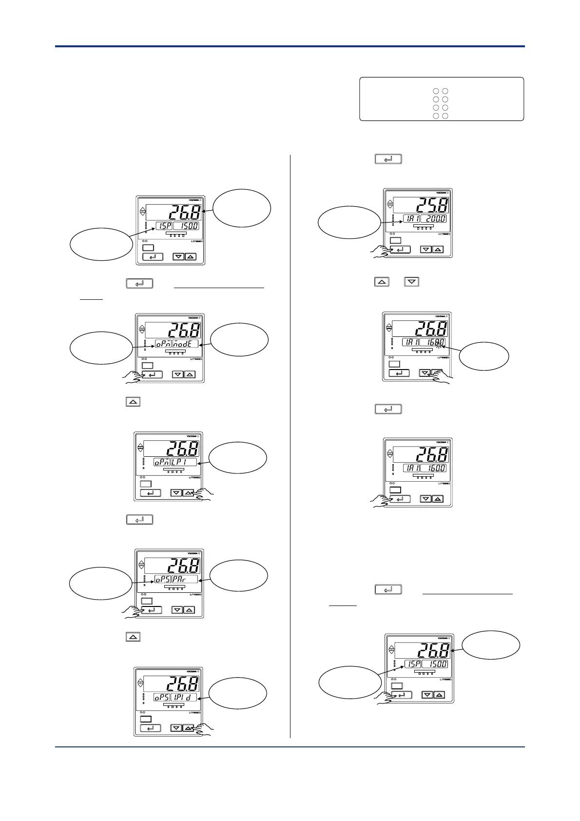
3.5 Setting Alarm Setpoints
The following operating procedure describes an
example of setting 160.0 to alarm-1 setpoint.
Check alarm type before setting the alarm setpoint.
When changing the alarm type, see “2.7 Chang-
ing Alarm Type,” .
1. Bring the operating display into view
(display appears at power on).
SET/ENT
A/M
PV
AL1 2 3 4
REM
CAS
MAN
LP2
Displays
target setpoint-1
“1.SP”.
Displays PV.
2. Press the
SET/ENT
key for more than 3 sec-
onds to call up the main menu “MODE”.
SET/ENT
A/M
PV
AL1 2 3 4
REM
CAS
MAN
LP2
Displays
main menu
“MODE”.
Displays symbol
“OP.M”.
3. Press the key once to display the main
menu “LP1”.
SET/ENT
A/M
PV
AL1 2 3 4
REM
CAS
MAN
LP2
Displays
main menu
“LP1”.
4. Press the
SET/ENT
key once to display the
submenu “PAR”.
SET/ENT
A/M
PV
AL1 2 3 4
REM
CAS
MAN
LP2
Displays
submenu
“PAR”.
Displays symbol
“OP.S”.
5. Press the key once to display the
submenu “1.PID”.
SET/ENT
A/M
PV
AL1 2 3 4
REM
CAS
MAN
LP2
Displays
submenu
“1.PID”.
6. Press the
SET/ENT
key twice to display the
parameter “1.A1”.
SET/ENT
A/M
PV
AL1 2 3 4
REM
CAS
MAN
LP2
Displays
parameter
“1.A1”
7. Press the or key to display the
required setpoint.
SET/ENT
A/M
PV
AL1 2 3 4
REM
CAS
MAN
LP2
Blinks during
change.
8. Press the
SET/ENT
key once to register the
setpoint.
SET/ENT
A/M
PV
AL1 2 3 4
REM
CAS
MAN
LP2
You can take the same steps for alarm-2
setpoint(1. A2), alarm-3 setpoint(1. A3),
alarm-4 setpoint(1. A4) that are displayed
after this.
9. Press the
SET/ENT
key for more than 3 sec-
onds. This returns you to the display
shown at power-on (figure below).
SET/ENT
A/M
PV
AL1 2 3 4
REM
CAS
MAN
LP2
Displays
target setpoint-1
“1.SP”.
Displays PV.
Alarm output terminals Factory-shipped settings
Alarm-1 (terminal numbers )............PV high limit alarm
Alarm-2 (terminal numbers )............PV low limit alarm
Alarm-3 (terminal numbers )............PV high limit alarm
Alarm-4 (terminal numbers )............PV low limit alarm
-
7
-
5 7
-
4 7
-
34
35
6

 Loading...


