<Toc> < 2. Initial Settings >
2-9
IM 05D01C02-41E 3rd Edition: May 31, 2006-00
2.4 Setting Control Output Type
(except for a Position Proportional Controller)
The following operating procedure describes an example of changing time proportional PID
relay output (0: factory-shipped value) to current output (2).
Control output terminal
For details on the output terminals for heating/cooling control, see “
”.
Values in parentheses are setpoints
Time proportional PID relay (0)/on-off(3) output
...........................
Current (2)/time proportional PID voltage pulse (1) output
.............
--
1 2 3
-
16
17
1.5
Terminal Wiring Diagrams
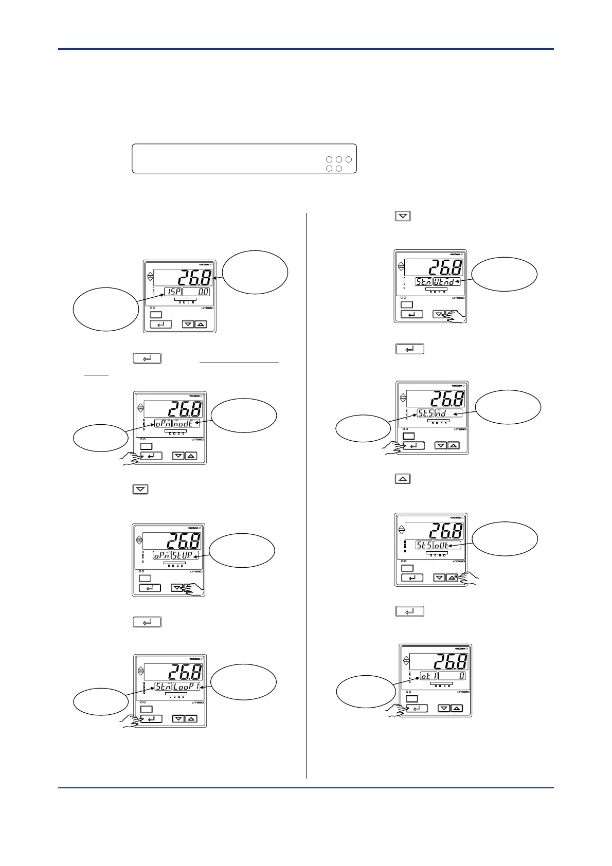
1. Bring the operating display into view
(display appears at power-on).
SET/ENT
A/M
PV
AL1 2 3 4
REM
CAS
MAN
LP2
Displays
target setpoint-1
“1.SP”.
Displays PV
2. Press the
SET/ENT
key for more than 3 sec-
onds to call up the main menu “MODE”.
SET/ENT
A/M
PV
AL1 2 3 4
REM
CAS
MAN
LP2
Displays main
menu “MODE”.
Displays
symbol “OP.M”.
3. Press the key once to display the main
menu “STUP”.
SET/ENT
A/M
PV
AL1 2 3 4
REM
CAS
MAN
LP2
Displays main
menu “STUP”.
4. Press the
SET/ENT
key once to display the
main menu “LOOP1”.
SET/ENT
A/M
PV
AL1 2 3 4
REM
CAS
MAN
LP2
Displays main
menu “LOOP1”.
Displays
symbol “ST.M”.
5. Press the key once to display the main
menu “UTMD”.
SET/ENT
A/M
PV
AL1 2 3 4
REM
CAS
MAN
LP2
Displays main
menu “UTMD”.
6. Press the
SET/ENT
key once to display the
submenu “MD”.
SET/ENT
A/M
PV
AL1 2 3 4
REM
CAS
MAN
LP2
Displays
submenu “MD”.
Displays
symbol “ST.S”.
7. Press the key twice to display the
submenu “OUT”.
SET/ENT
A/M
PV
AL1 2 3 4
REM
CAS
MAN
LP2
Displays
submenu
“OUT”.
8. Press the
SET/ENT
key once to display the
parameter “OT1” (control output type).
SET/ENT
A/M
PV
AL1 2 3 4
REM
CAS
MAN
LP2
Displays
parameter
“OT1”.

 Loading...


