5-14
<Toc> < 5. Parameters >
IM 05D01C02-41E 3rd Edition: May 31, 2006-00
● Control Action-related Parameters
Located in: Main menu =
(LOOP1)
; Submenu =
(CTL)
(OPR)
(MOD)
(AR)
(ZON)
(R.MD)
(R.TM)
(GRP)
0: Standard PID control (with output bump at SP change)
1: Fixed -point control (without output bump at SP change)
Choose “Fixed-point Control” when controlling pressure or flow rate.
Output velocity
limiter
OFF (0)
0.1 to 100.0%/sec
can limit control output velocity
PID control mode
Anti-reset windup
(Excess integration
prevention)
AUTO (0), 50.0 to 200.0%
The larger Setting, the sooner PID computation (integral computation) stops.
Used when the control output travels up to 100% or down to 0% and
stays at this point.
Zone PID selection
0: SP selection
1: Zone PID
If set to “SP selection,” allows PID constants to be selected for each
target setpoint.
If set to “Zone PID,” automatically selects PID constants according
to the temperature range set in the given Reference Point parameter.
Restart mode
Restart timer
CONT (0): Continues action set before power failure.
MAN (1): Starts from manual operation status
AUTO (2): Continues action set before power failure in automatic operation.
Allows you to determine how the controller should recover from a power
failure of longer than 2 sec
.
0 to 10 sec.
Sets time between power on and the instant where controller
starts computation.
PID group number
Zone PID reference
point-1
Zone PID reference
point-2
Zone PID reference
point-3
Zone PID reference
point-4
Zone PID reference
point-5
Zone PID reference
point-6
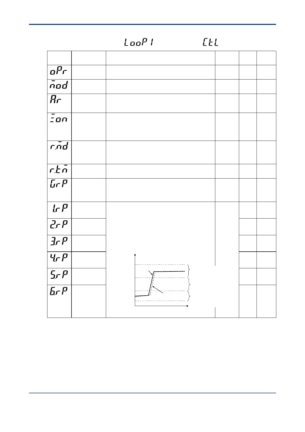
0.0 to 100.0% of PV input range.
Note that 1.RP 2.RP 3.RP 4.RP 5.RP 6.RP.
Sets reference points at which switching is carried out between groups
of PID constants according to the given temperature zone. You can set
a maximum of six reference points and therefore a maximum of seven
temperature zones. To enable this parameter, set the Zone PID
Selection (ZON) parameter to “1”.
The example below sets reference points 1 and 2 to provide 3 zones to
switch PID constants automatically.
Time
Maximum value of
PV input range
RH1
Reference point 2
2.RP
Minimum value of
PV input range
RL1
Reference point 1
1.RP
PV input
value
Setpoint
Allows you to determine how many groups of setpoint, alarm and
PID parameters the controller should show.
1: Show one set. 2: Show two sets.
3: Show three sets. 4: Show four sets.
5 to 8: Show as many groups of parameters as have been set.
OFF (0)
AUTO (0)
0
0
CONT (0)
0 sec.
8
100.0% of
PV input
range
Parameter
Symbol
Name of Parameter Setting Range and Description Initial Value User
Setting
Target Item
in CD-ROM
(1.RP)
(2.RP)
(3.RP)
(4.RP)
(5.RP)
(6.RP)
Zone 3
The controller is operated with
the 3rd group of PID constants.
Zone 2
The controller is operated with
the 2nd group of PID constants.
Zone 1
The controller is operated with
the 1st group of PID constants.
Ref.2.1(2)
Ref.2.1(4)
Ref.4.1(2)
Ref.4.1(1)
Ref.4.1(2)
Same as
above
Same as
above
Same as
above
Same as
above
Same as
above

 Loading...


