<Toc> < 2. Initial Settings >
2-1
IM 05D01C02-41E 3rd Edition: May 31, 2006-00
2. Initial Settings
This chapter describes examples of setting PV input types, control output types, and
alarm types. Carrying out settings described herein allows you to perform basic
control. Refer to examples of various settings to understand how to set parameters
required. Refer to “5.1 Parameter Map” for an easy to understand explanation of
setting various parameters. If you cannot remember how to carry out an operation
during setting, press the
SET/ENT
key for more than 3 seconds. This brings you to the
display (operating display) that appears at power-on.
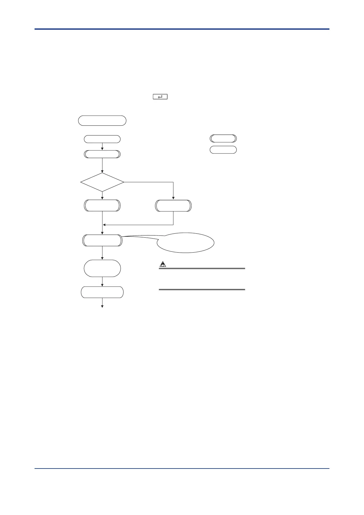
Power-on
Set the alarm
type and other setup
parameters.
See “2.2 Setting PV Input Type (Setting First at Power-on),”
or “2.3 Changing PV Input Type.”
Calibrate valve
position.
Set the control
output.
(Factory-set to “Time Proportional Relay Output.”)
(Factory-set to “Unspecified.”)
Initialize
parameters.
Denotes a step that must always be followed.
Denotes a step that should be followed as necessary.
Setup Procedure
Yes
Set operating
parameters.
Controller operation
See “2.4 Setting Control Output Type.”
See “2.5 Calibrating Valve Position.”
See “2.6 Initializing Parameters.”
Set PV input.
No
Be sure to follow this
step whenever a chang of setting
is made to the PV input type.
Position
proportional
controller?
When initializing parameters is excuted, the controller initializes
the operating parameter and setup parameters. Therefore, check
that the appropriate value are set for the parameters after
initializing parameters. If changed to initial values, set them to the
appropriate values again.
NOTE
The following explanation of operation for the UT550’s panel, shown in the figure, is the
same as that of the UT520’s panel.

 Loading...


