<Toc> < 1. Installation >
1-9
IM 05D01C02-41E 3rd Edition: May 31, 2006-00
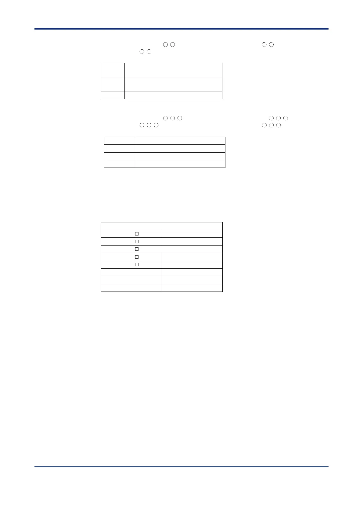
• Voltage pulse output
(Standard type: terminals
16
-
17
; heating-side output: terminals
16
-
17
, cooling-side
output: terminals
46
-
47
)
Number of
outputs
1 or 2 (two for heating/cooling type),
switched between a voltage pulse output and current output.
Output signal
On-voltage = 12 V or more (load resistance: 600 Ω or more)
Off-voltage = 0.1 V DC or less
Resolution
10 ms or 0.1% of output, whichever is larger
• Relay contact output
(Standard type: terminals
1
-
2
-
3
, heating-side output: terminals
1
-
2
-
3
, cooling-side
output: terminals
48
-
49
-
50
, position proportional type: terminals
48
-
49
-
50
)
Number of outputs
1 or 2(two for heating/cooling type)
Output signal Three terminals (NC, NO, and common)
Contact rating 250 V AC or 30 V DC, 3 A (resistance load)
Resolution 10 ms or 0.1% of output, whichever is larger
Contact Inputs
• Purpose: Target setpoint selection, remote/local mode switching, and run/stop
switching
• Number of inputs: Differs with model and suffix codes as shown in the table below.
Model and Suffix Codes Number of Inputs
UT520-00
UT520-07
UT520-08
2
8
3
7
3
2
4
4
UT550- 0
UT550- 1
UT550- 2
UT550- 3
UT550- 4
• Input type: Non-voltage contact or transistor open collector input
• Input contact rating: 12 V DC, 10 mA or more
• On/off determination: For non-voltage contact input, contact resistance of 1 k or less
is determined as “on” and contact resistance of 20 k or more as “off.”
For transistor open collector input, input voltage of 2 V or less is determined as “on”
and leakage current must not exceed 100 A when “off.”
• Minimum status detection hold time: PV input’s sampling period 3

 Loading...


