5-4
<Toc> < 5. Parameters >
IM 05D01C02-41E 3rd Edition: May 31, 2006-00
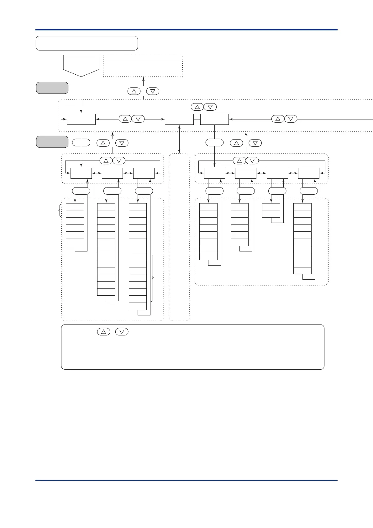
LOOP1
Main menu
Submenu
AL4
AL3
AL2
AL1
HY3
HY2
HY1
DY1
HY4
DY3
DY2
DY4
AMD
ALM CTL
SET
ZON
AR
MOD
Same as
LOOP1
OPR
GRP
R.TM
R.MD
2.RP
1.RP
4.RP
3.RP
5.RP
RHY
6.RP
RDV
SET
TMU
PVT
SPT
RMS
SPL
SPH
SET
SP
SET
CMLP
RT2
TL1
TH1
RT1
TL2
TH2
RET LOCK
SET
LP1
MOD
A/M
DAT
USR
PID
LP2
PY2
PY1
PWD
SET
LC1
SR1
FL1
BS1
LC3
SR3
SET
AIN
SET
LOOP2
Password
check
display
OK
To operating parameter setting
display main menu [MODE]
(on the previous page)
FL3
BS3
TRND
DV2
DVB
SET
++
+
*1 Parameters RMS and SPT are displayed only for the controller with auxiliary analog (remote) input.
*2 Displayed when parameter ZON is “1.”
*3 Main menu LOOP2 is displayed when UT mode is “Cascade control.”
*4 Submenu R485 is displayed only for the controller with communication functions.
*5 Submenu VALV is displayed for the position proportional controller
*3
*2
*1
Pressing the + keys when a parameter setting display is shown retrieves the menu of that
parameter setting display.
The parameter codes of the UT550/UT520 are different from the characters actually
displayed on the LED indicator. Refer to "5.2 Lists of Parameters" for the corresponding indicator
characters.
Note:
UT550/UT520 Setup Parameter Map
However,
RMS,
ZON,
R.MD,
R.TM
are not
contained.

 Loading...


