<Toc> < 5. Parameters >
5-5
IM 05D01C02-41E 3rd Edition: May 31, 2006-00
CONF
DO4
DO3
DO2
DO1
DO7
DO6
DO5
DO DI
SET
CAS
S/R
R/L
A/M
SP.0
MAN
AUT
SP.2
SP.1
SP.3
SET
C.S4
C.S3
C.S2
C.S1
C.S5
SET
CSEL
SET
UTMD
RL1
RH1
UN1
IN1
P.L1
P.H1
P.D1
P.U1
P.L2
P.H2
P.D2
P.U2
RJC
BO1
SL1
SH1
DP1
RL3
RH3
UN3
IN3
BO3
SL3
SH3
DP3
IN VALV
SET
V.H
V.L
V.RS
V.AT
V.MD
TR.T
SET
SMC
SMP
UTM
SET
MD
SET
OUT
OT2
OT1
CTc
CT
AO2
AO1
AO3
SET
R485
STP
PRI
BPS
PSL
RP.T
ADR
DLN
SET
A1H
A1L
A2H
A2L
A3H
A3L
TEST INIT
INI
SET
+ +
*5*4
This item is
not to be set.
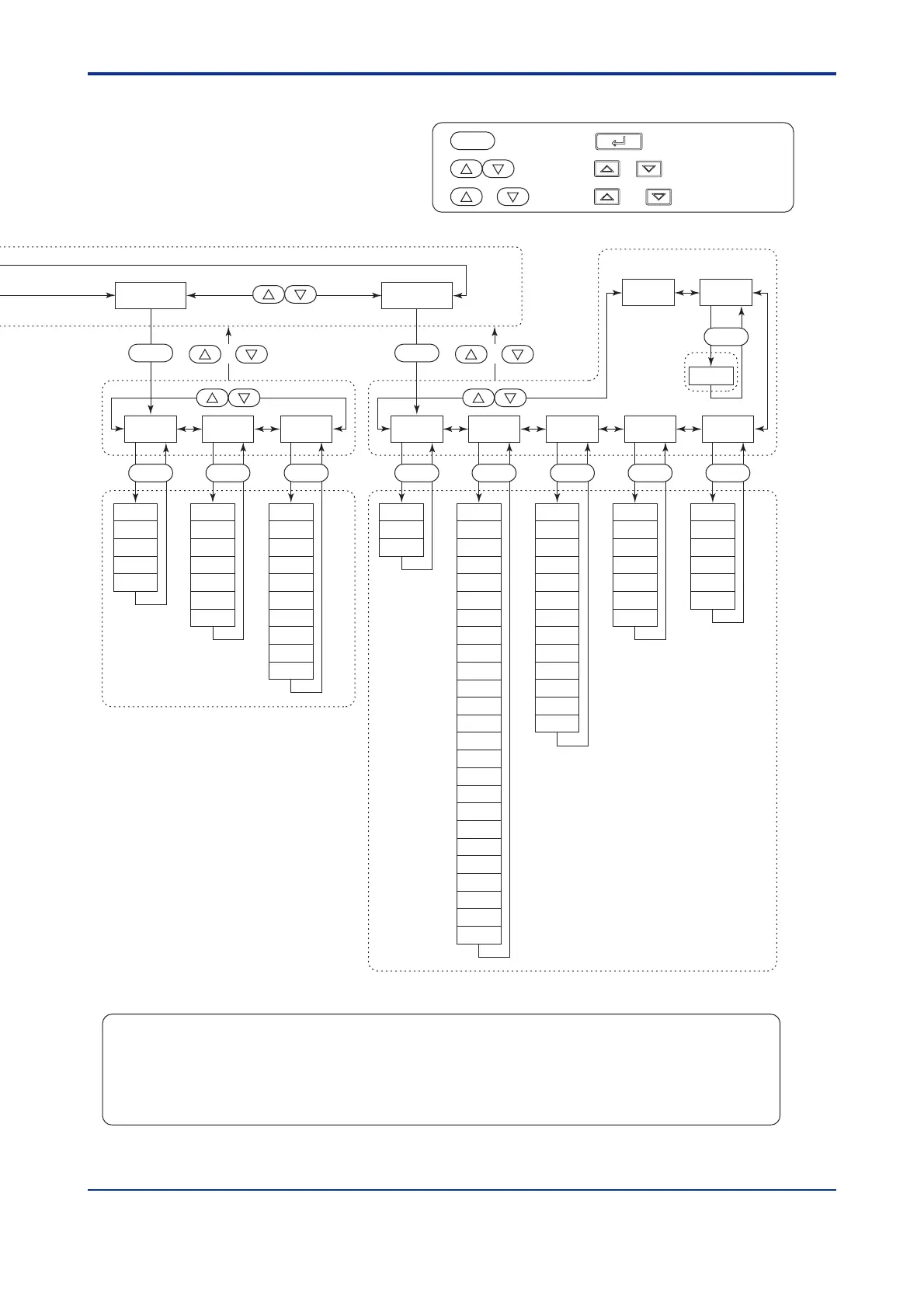
: Press the key once.
: Press the or key once.
: Press the and keys simultaneously.
SET
+
SET/ENT
The parameter items shown on the [TEST] submenu of the setup parameter display are to be used
by Yokogawa service personnel to check the controller functions. Users cannot set or change these
parameters.
Note:
The parameter codes of the UT550/UT520 are different from the characters actually displayed on
the LED indicator. Refer to "5.2 Lists of Parameters" for the corresponding indicator characters.
Note:

 Loading...


