<Toc> < 2. Initial Settings >
2-3
IM 05D01C02-41E 3rd Edition: May 31, 2006-00
2.2 Setting PV Input Type (Setting First at Power-on)
NOTE
• The controller displays an operating display when the power is turned on. The
submenu “IN” appears at this point if the type of PV input has not been defined yet. In
this case, first press the
SET/ENT
key once to display the parameter “IN1” for the PV input
type, and use the
key to display the input range code to use, then press the
SET/ENT
key to register it. Then, set the maximum value (RH1) and minimum value (RL1) of
the PV input range (for voltage input, set the maximum value (SH1) and minimum
value (SL1) of the PV input scale). See the operating procedure below for more details.
• The controller is configured to the default of each parameter at the factory before
shipment.
First check these defaults listed in “5.2 Lists of Parameters”, and change their values if
necessary.
Minimum value of
PV input range (RL1)
Instrument
input range
-270.0°C 1370.0°C
0.0°C 800.0°C
Maximum value of
PV input range (RH1)
Minimum value of
PV input scale (SL1)
1V 5V (input signal)
0.0m
3
/h 50.0m
3
/h
Maximum value of
PV input scale (SH1)
2V 4V
RL1
RH1
Parameters to be set for temperature input
1. PV input type (IN1): Set according to a sensor
2. Maximum value of PV input range (RH1): Set the
maximum value of the range to be controlled.
3. Minimum value of PV input range (RL1): Set the
minimum value of the range to be controlled.
Parameters to be set for voltage input
1. PV input type (IN1): Set according to an input signal
2. Maximum value of PV input range (RH1): Set the maximum value of an input signal.
3. Minimum value of PV input range (RL1): Set the minimum value of an input signal.
4.
Position of PV input decimal point (DP1): Set the position of the decimal point for PV input display.
5. Maximum value of PV input scale (SH1): Set the maximum value of the scale to be controlled.
6. Minimum value of PV input scale (SL1): Set the minimum value of the scale to be controlled.
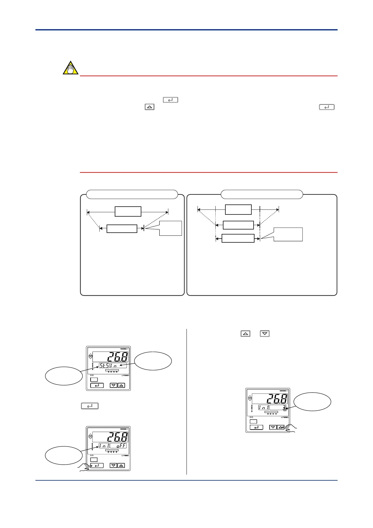
Set a range
to be
controlled
Set a range to
be controlled
PV input range
PV input range
PV input scale
Instrument
input range
Example of Temperature Input Example of Voltage Input
The following operating procedure describes an example of setting a K-type thermocouple
(-200.0 to 500.0˚C) and a measurement range of 0.0 to 200.0˚C.
1. Display view at power-on
SET/ENT
A/M
PV
AL1 2 3 4
REM
CAS
MAN
LP2
Displays
submenu “IN”.
Displays
symbol “
ST.S
”.
2. Press the
SET/ENT
key once to display the
parameter IN1 (PV input type).
SET/ENT
A/M
PV
AL1 2 3 4
REM
CAS
MAN
LP2
Displays
parameter “IN1”.
3. Press the or key to display the
required setpoint.
The figure below shows an example of
setting a K-type thermocouple (-200.0°C to
500.0°C). See “Instrument Input Range
Codes.”
SET/ENT
A/M
PV
AL1 2 3 4
REM
CAS
MAN
LP2
Blinks during
change.

 Loading...


