2-4
<Toc> < 2. Initial Settings >
IM 05D01C02-41E 3rd Edition: May 31, 2006-00
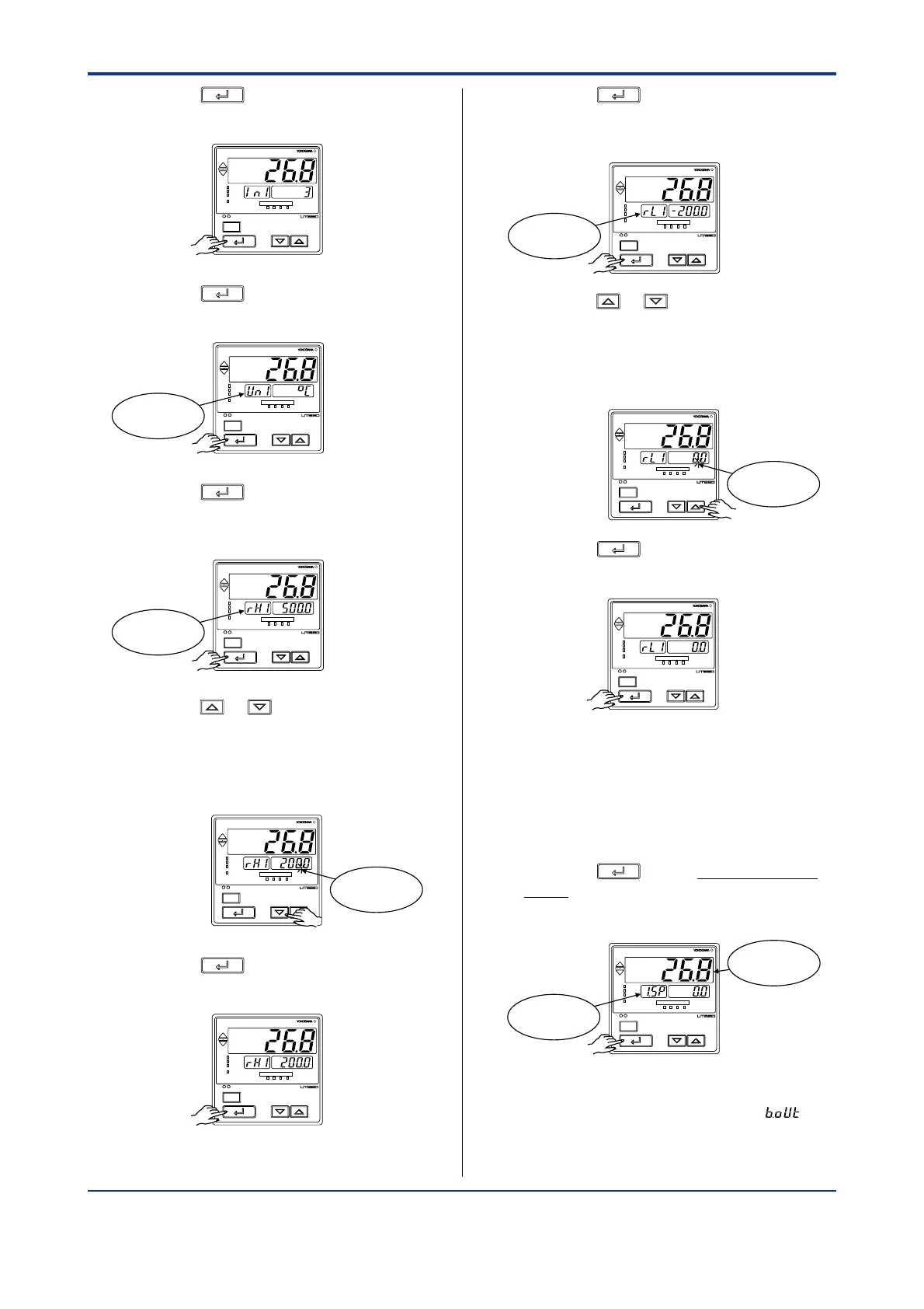
4. Press the
SET/ENT
key once to register the
setpoint.
SET/ENT
A/M
PV
AL1 2 3 4
REM
CAS
MAN
LP2
5. Press the
SET/ENT
key once to display the
parameter “UN1” (PV input unit).
SET/ENT
A/M
PV
AL1 2 3 4
REM
CAS
MAN
LP2
Displays
parameter “UN1”.
6. Press the
SET/ENT
key once to display the
parameter “RH1” (maximum value of PV
input range).
SET/ENT
A/M
PV
AL1 2 3 4
REM
CAS
MAN
LP2
Displays
parameter “RH1”.
7. Press the or key to display the
required setpoint.
The figure below shows an example of
setting the maximum value of the PV input
range to 200.0°C.
SET/ENT
A/M
PV
AL1 2 3 4
REM
CAS
MAN
LP2
Blinks during
change.
8. Press the
SET/ENT
key once to register the
setpoint.
SET/ENT
A/M
PV
AL1 2 3 4
REM
CAS
MAN
LP2
9. Press the
SET/ENT
key once to display the
parameter “RL1” (minimum value of PV
input range).
SET/ENT
A/M
PV
AL1 2 3 4
REM
CAS
MAN
LP2
Displays
parameter “RL1”.
10. Press the or key to display the
required setpoint.
The figure below shows an example of
setting the minimum value of the PV input
range to 0.0°C.
SET/ENT
A/M
PV
AL1 2 3 4
REM
CAS
MAN
LP2
Blinks during
change.
11. Press the
SET/ENT
key once to register the
setpoint.
SET/ENT
A/M
PV
AL1 2 3 4
REM
CAS
MAN
LP2
If the type of input is voltage, also config-
ure the PV Input Decimal Point Position
(DP1), Maximum Value of PV Input Scale
(SH1) and Minimum Value of PV Input Scale
(SL1) parameters that follow this step.
12. Press the
SET/ENT
key for more than 3 sec-
onds. This returns you to the display
shown at power-on (figure below).
SET/ENT
A/M
PV
AL1 2 3 4
REM
CAS
MAN
LP2
Displays
target setpoint-1
“1.SP”.
Displays PV
The PV display in the figure above shows
the error code for input burnout ( ) if
PV input wiring is not yet complete. The
error code disappears when you wire the
PV input terminals correctly.

 Loading...


