<Toc> < 5. Parameters >
5-13
IM 05D01C02-41E 3rd Edition: May 31, 2006-00
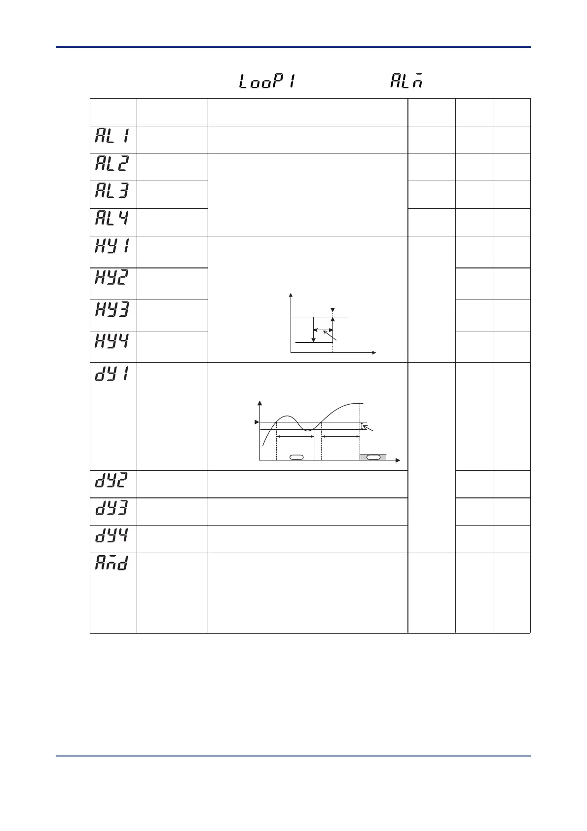
● Alarm-related Parameters
Located in: Main menu =
(LOOP1)
; Submenu =
(ALM)
Alarm-1 type
Alarm-2 type
Alarm-3 type
Alarm-4 type
1
2
1
2
Parameter
Symbol
Name of Parameter Setting Range and Description Initial Value User
Setting
Target Item
in CD-ROM
(AL1)
(AL2)
(AL3)
(AL4)
Alarm-1 hysteresis 0.5% of PV
input range
span
Output
alarm: 0.5%
Point of ON/OFF action
(Alarm setpoint)
Hysteresis
PV value
Output
Hysteresis for PV high limit alarm
On
Off
(HY1)
(HY4)
(HY2)
(HY3)
Alarm-2 hysteresis
Alarm-3 hysteresis
Alarm-4 hysteresis
OFF (0), 1 to 31
(same as below)
Common to all target setpoints.
OFF (0), 1 to 20, 25 to 31
1: PV high limit (energized, no stand-by action)
2: PV low limit (energized, no stand-by action)
3: Deviation high limit (energized, no stand-by action)
4: Deviation low limit (energized, no stand-by action)
5: Deviation high limit (de-energized, no stand-by action)
6: Deviation low limit (de-energized, no stand-by action)
For other alarm types, see “2.7 Changing Alarm Type.”
Common to all target setpoints.
0.0 to 100.0% of PV input range span
Output alarm: 0.0 to 100.0%
Allows margins to be set for an alarm setpoint.
With the hysteresis settings, it is possible to prevent relays from chattering.
0.00
0
(DY1)
(DY2)
(DY3)
(DY4)
(AMD)
Alarm-1 delay timer
Alarm-2 delay timer
Alarm-3 delay timer
Alarm-4 delay timer
Alarm mode
0.00 to 99.59 (min, sec.) (enabled when alarm-1 type “AL1” is 1
to 20 or 28 to 31)
An alarm is output when the delay timer expires after the alarm
setpoint is reached.
0.00 to 99.59 (min, sec.) (enabled when alarm-2 type “AL2” is 1
to 20 or 28 to 31)
0.00 to 99.59 (min, sec.) (enabled when alarm-3 type “AL3” is 1
to 20 or 28 to 31)
0.00 to 99.59 (min, sec.) (enabled when alarm-4 type “AL4” is 1
to 20 or 28 to 31)
Allows the alarm function to be enabled or disabled according to
the operating condition.
0: Always active
1: Not active when in Stop mode
2: Not active when in Stop mode or manual operation
3: Eight alarms are used and always enabled.
4:
Eight alarms are used and disabled when the controller is at a stop.
5: Eight alarms are used and disabled when the controller is at
a stop or in manual operation.
Ref.3.3(3)
Ref.3.3(4)
Ref.3.3(4)
Ref.3.3(2)
Ref.3.3(1)
Same as
above
Same as
above
Same as
above
Same as
above
Same as
above
Time
Hysteresis
Alarm setpoint
Alarm output
Delay timer
PV
onoff
Delay timer

 Loading...


