<Toc> < 2. Initial Settings >
2-7
IM 05D01C02-41E 3rd Edition: May 31, 2006-00
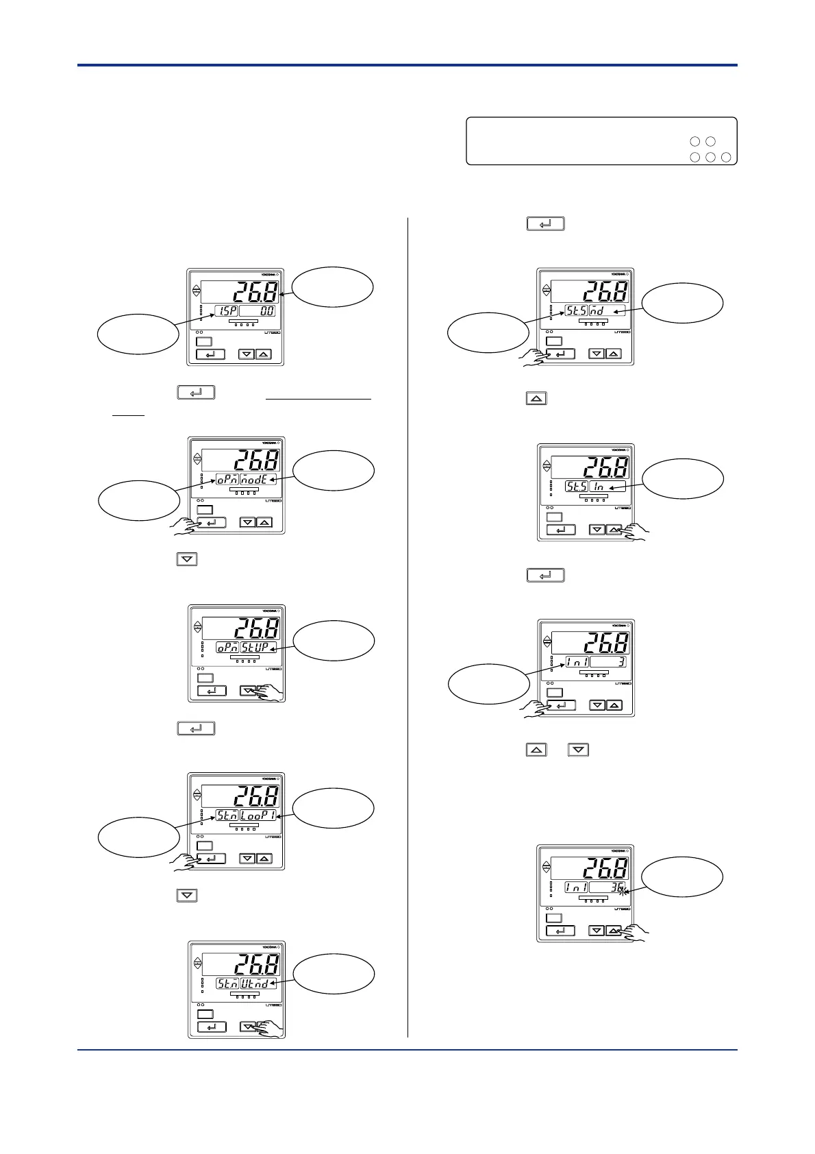
1. Bring the operating display into view
(display appears at power-on).
SET/ENT
A/M
PV
AL1 2 3 4
REM
CAS
MAN
LP2
Displays PV
Displays
target setpoint-1
“
1.SP
”
.
2. Press the
SET/ENT
key for more than 3 sec-
onds to call up the main menu “MODE”.
SET/ENT
A/M
PV
AL1 2 3 4
REM
CAS
MAN
LP2
Displays
symbol
“
OP.M
”
.
Displays main
menu “MODE”.
3. Press the key once to display the main
menu “STUP”.
SET/ENT
A/M
PV
AL1 2 3 4
REM
CAS
MAN
LP2
Displays main
menu “STUP”.
4. Press the
SET/ENT
key once to display the
main menu “LOOP1”.
SET/ENT
A/M
PV
AL1 2 3 4
REM
CAS
MAN
LP2
Displays
symbol
“
ST.M
”
.
Displays main
menu “LOOP1”.
5. Press the key once to display the main
menu “UTMD”.
SET/ENT
A/M
PV
AL1 2 3 4
REM
CAS
MAN
LP2
Displays main
menu “UTMD”.
6. Press the
SET/ENT
key once to display the
submenu “MD”.
SET/ENT
A/M
PV
AL1 2 3 4
REM
CAS
MAN
LP2
Displays
submenu “MD”.
Displays
symbol
“
ST.S
”
.
7. Press the key once to display the
submenu “IN”.
SET/ENT
A/M
PV
AL1 2 3 4
REM
CAS
MAN
LP2
Displays
submenu “IN”.
8. Press the
SET/ENT
key once to display the
parameter “IN1” (PV input type).
SET/ENT
A/M
PV
AL1 2 3 4
REM
CAS
MAN
LP2
Displays
parameter “IN1”.
9. Press the or key to display the
required setpoint. The figure below shows
an example of setting the PV input type to a
Pt100 resistance temperature detector
(-200.0°C to 500.0°C).
SET/ENT
A/M
PV
AL1 2 3 4
REM
CAS
MAN
LP2
Blinks during
change.
PV input terminal
Thermocouple/mV/V input
..............................
RTD input .................................................. --
131211
-
1312
2.3 Changing PV Input Type
The following operating procedure de-
scribes an example of changing the setting
of K-type thermocouple (-200.0 to 500.0˚C)
to RTD Pt100
(-200.0 to 500.0˚C) and a measurement range of 0.0 to 200.0˚C.

 Loading...


