<Toc> < 2. Initial Settings >
2-11
IM 05D01C02-41E 3rd Edition: May 31, 2006-00
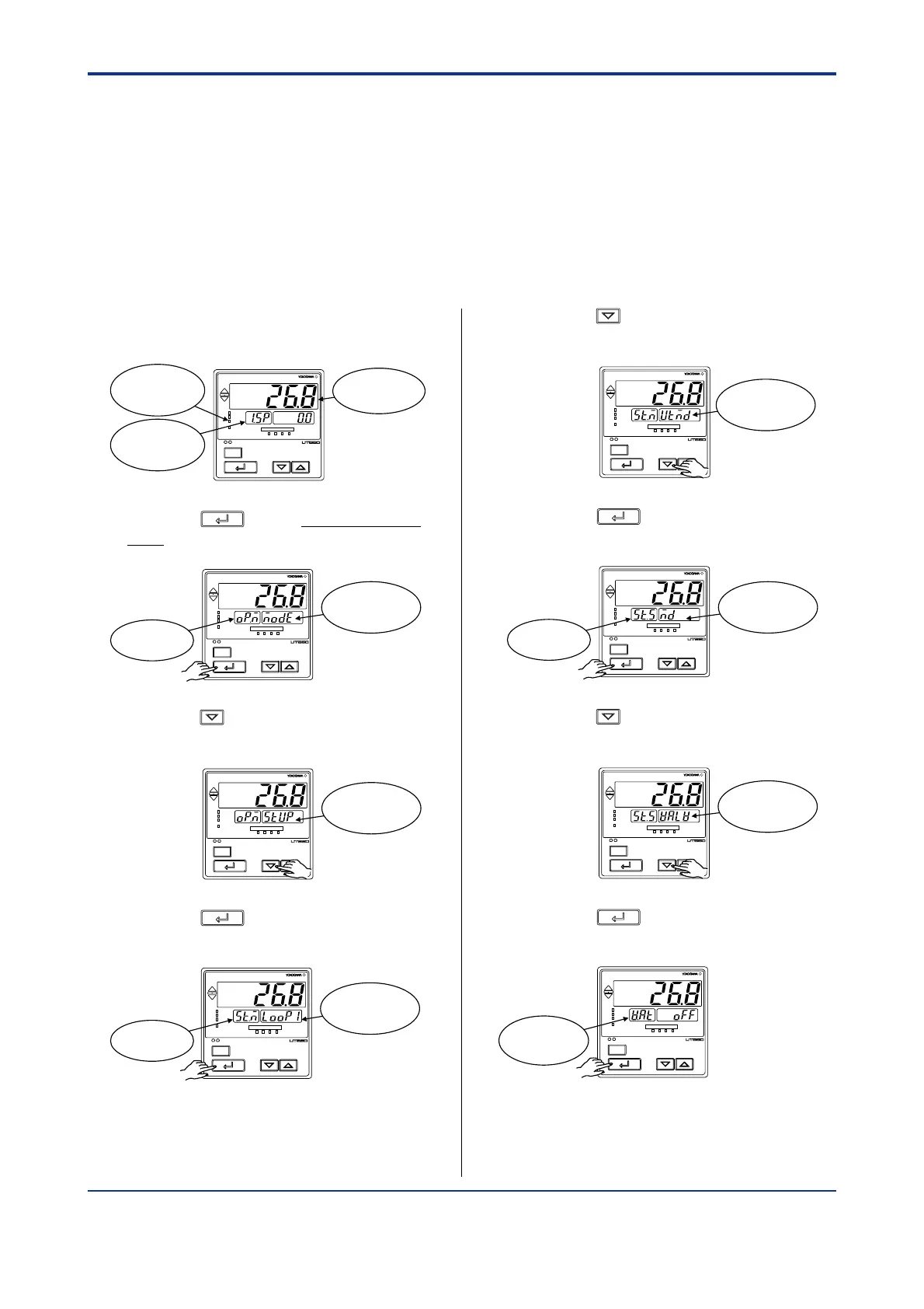
1. Bring the operating display into view
(display appears at power-on).
SET/ENT
A/M
PV
AL1 2 3 4
REM
CAS
MAN
LP2
Displays
target setpoint-1
“1.SP”.
MAN lamp
ON.
Displays PV
2. Press the
SET/ENT
key for more than 3 sec-
onds to call up the main menu “MODE”.
SET/ENT
A/M
PV
AL1 2 3 4
REM
CAS
MAN
LP2
Displays
symbol “OP.M”.
Displays
main menu
“MODE”.
3. Press the key once to display the main
menu “STUP”.
SET/ENT
A/M
PV
AL1 2 3 4
REM
CAS
MAN
LP2
Display
main menu
“STUP”.
4. Press the
SET/ENT
key once to display the
main menu “LOOP1”.
SET/ENT
A/M
PV
AL1 2 3 4
REM
CAS
MAN
LP2
Displays
symbol “ST.M”.
Displays
main menu
“LOOP1”.
2.5 Calibrating Valve Position
(for a Position Proportional Controller Only)
The following operation describes a procedure of inputting a feedback signal from a control
valve to calibrate the full closed and full open positions of the valve automatically. To cali-
brate the valve position, you need to carry out wire connections and bring the controller into
manual mode. For connections, see “1.5 Terminal Wiring Diagrams” and for entering the
manual mode, see “3.8 Switching between AUTO and MAN” .
5. Press the key once to display the main
menu “UTMD”.
SET/ENT
A/M
PV
AL1 2 3 4
REM
CAS
MAN
LP2
Displays main
menu “UTMD”.
6. Press the
SET/ENT
key once to display the
submenu “MD”.
SET/ENT
A/M
PV
AL1 2 3 4
REM
CAS
MAN
LP2
Displays
symbol “ST.S”.
Displays
submenu “MD”.
7. Press the key three times to display the
submenu “VALV”.
SET/ENT
A/M
PV
AL1 2 3 4
REM
CAS
MAN
LP2
Displays
submenu
“VALV”.
8. Press the
SET/ENT
key once to display the
parameter “V.AT”.
SET/ENT
A/M
PV
AL1 2 3 4
REM
CAS
MAN
LP2
Displays
parameter
“V.AT”.

 Loading...


