4-2
<Toc> < 4. Troubleshooting and Maintenance >
IM 05D01C02-41E 3rd Edition: May 31, 2006-00
■ Errors at Power On
The following table shows errors that may be detected by the fault diagnosis function when
the power is turned on.
Error indication
(on PV display unit)
Description
of error
Remedy
Faulty RAM
Faulty ROM
System data error
2
Setpoint display unit
Error code 21 is displayed.
Bit No. 6–
–
543210
Error Code
2
2
2
1
2
0
2
3
2
2
2
1
2
0
1
12
PV decimal point blinks.
Faulty calibration
value
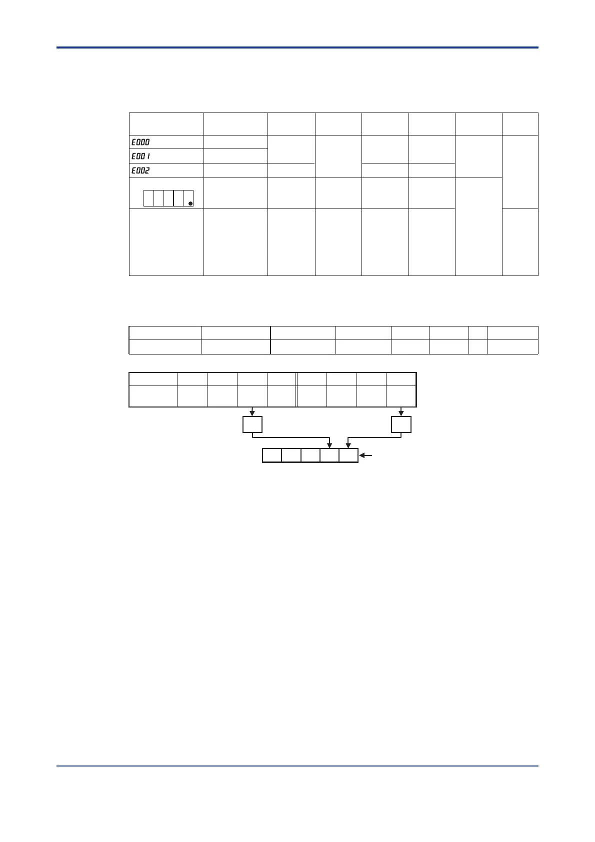
An error code is displayed in the event of an error, according to its type.
An error code is a two-digit figure in which a combination of 6 bits of on and off is converted into a decimal number.
The following shows the relationship between each bit and parameter to be checked for abnormality.
Note : An error code is displayed on the setpoint display unit.
Bit No.
65432
1
0
Parameter to be checked Operation mode/output Operating parameters Setup parameters
Range data UT mode Calibration data
For example, if an error occurs with the operating parameter and calibration data, the error code will be as follows:
PV
Control
output
Alarm
output
Retransmission
output
Communication
None OFF 0% or less
Undefined
0% or less
or OFF
Undefined Undefined
Normal
action
Faulty
Contact us
for repair.
Check and
set the
initialized
parameters.
Normal action
(out of
accuracy)
Normal action
(out of
accuracy)
Normal action
(out of
accuracy)
Normal action
(out of
accuracy)
Error code (Note)
(See description below.)
Parameter error
Normal action Normal action Normal action Normal action
(E000)
(E001)
(E002)
–
Stopped

 Loading...


