5-20
<Toc> < 5. Parameters >
IM 05D01C02-41E 3rd Edition: May 31, 2006-00
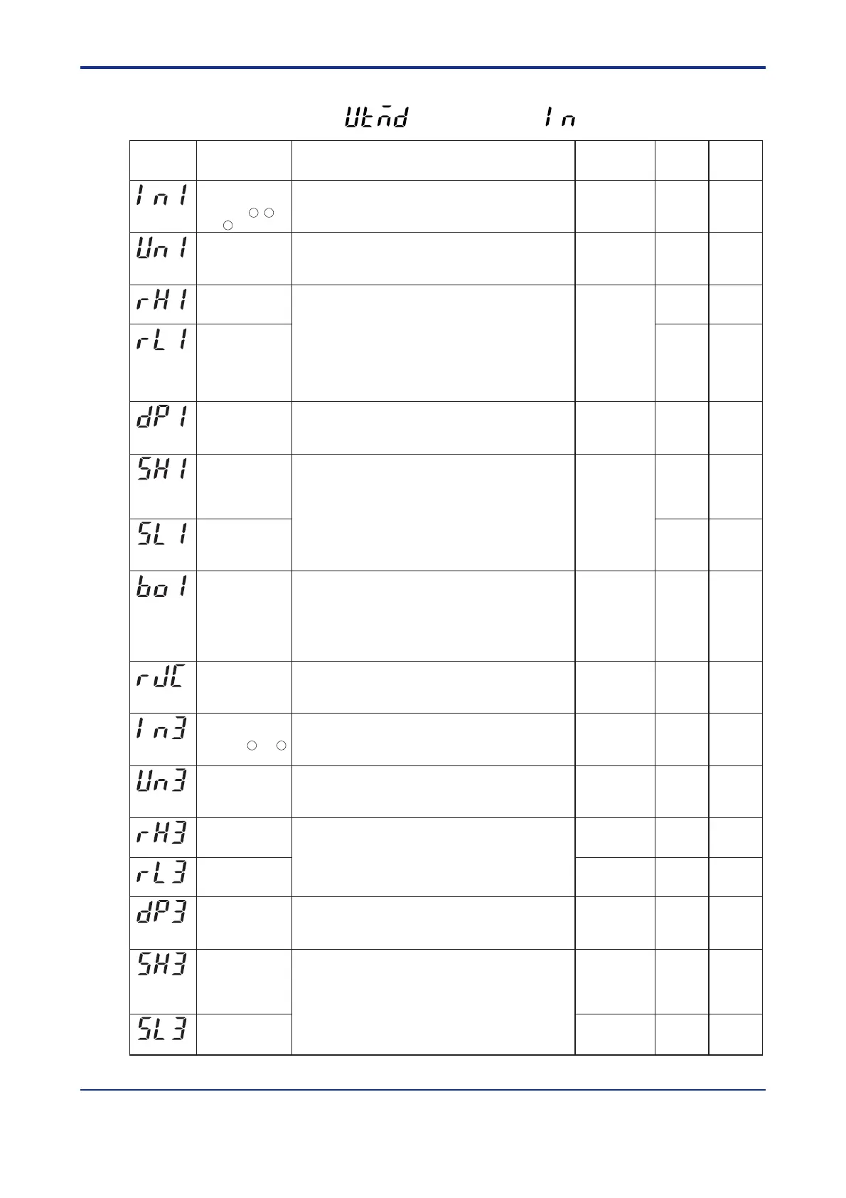
● Input-related Parameters
Located in: Main menu =
(UTMD)
; Submenu =
(IN)
Parameter
Symbol
Name of Parameter Setting Range and Description Initial Value
PV input type
(INPUT 1 terminals)
Terminals ,
and
Specify the type of PV input as a range code.
OFF (0), 1 to 18, 30, 31, 35 to 37, 40, 41, 50, 51, 55, 56
See “Instrument Input Range Codes” in “2. Initial Settings”.
OFF (0)
PV input unit Select the unit of PV input.
% (0): Percent F (5): Fahrenheit
C (1): Degree Celsius
- (2): No unit
User
Setting
Target Item
in CD-ROM
(IN1)
Max. value of PV
input range
Set the PV input range (RL1 < RH1).
- For temperature input -
Set the range of temperature that is actually controlled.
- For voltage input -
Set the range of a voltage signal that is applied.
The scale across which the voltage signal is actually controlled
should be set using the parameters Maximum Value of PV Input
Scale (SH1) and Minimum Value of PV Input Scale (SL1).
Depends on
the PV
input type.
Depends on
the PV
input type.
(UN1)
(RH1)
Min. value of PV
input range
PV input decimal
point position
(shown when in
voltage-input mode)
Set the position of the decimal point of voltage-mode PV input.
0 to 4
Depends on
the PV
input type.
Depends on
the PV
input type.
(RL1)
Max. value of PV
input scale
(shown when in
voltage-input mode)
Set the read-out scale of voltage-mode PV input.
-19999 to 30000, where SL1 < SH1, SH1 - SL1 <= 30000
(DP1)
(SH1)
Min. value of PV
input scale
(shown when in
voltage-input mode)
Selection of PV
input burnout action
Allows the PV input value to be determined as shown below in
case of PV input burnout.
• 105% of PV input range if set to “Upscale”
• -5.0% of PV input range if set to “Downscale”
OFF (0): Disable
UP (1): Upscale
DOWN (2): Downscale
Depends on
the PV
input type.
(SL1)
Presence/absence
of PV input
reference junction
compensation
Allows input compensation to be applied to thermocouple input.
OFF (0): Absent
ON (1): Present
ON (1)
(BO1)
(RJC)
Remote input type
(INPUT 3 terminals)
Terminals and
Specify the type of remote input as a range code.
40, 41, 50, 51
See “Instrument Input Range Codes” in “2. Initial Settings”.
41
Remote input unit Select the unit of remote input.
% (0): Percent F (5): Fahrenheit
C (1): Degree Celsius
- (2): No unit
% (0)
(IN3)
(UN3)
Maximum value
of remote input
range
Set the range of a voltage signal. (RL3 < RH3)
5.000
1.000
(RH3)
Minimum value of
remote input range
Remote input
decimal point
position
Set the position of the decimal point for remote input.
0 to 4
Same as the
position of
the PV input's
decimal point
Maximum value
of PV input
scale
Minimum value
of PV input
scale
(RL3)
Max. value of
remote input scale
Set the remote input read-out scale.
-19999 to 30000, where SL3 < SH3, SH3 - SL3 <= 30000
Under normal operation, set the values of these parameters as
shown below.
- When PV input is temperature -
Maximum and minimum values of PV input range
- When PV input is voltage -
Maximum and minimum values of PV input scale
(DP3)
(SH3)
Min. value of
remote input scale
(SL3)
11 12
13
21 22
Ref.1.2(1)
Same as
above
Same as
above
Same as
above
Same as
above
Same as
above
Same as
above

 Loading...


