2-14
<Toc> < 2. Initial Settings >
IM 05D01C02-41E 3rd Edition: May 31, 2006-00
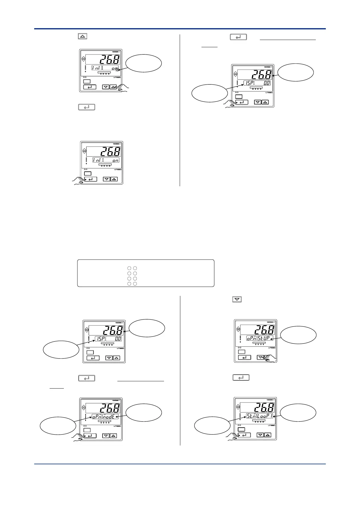
9. Press the key to display “ON”.
SET/ENT
A/M
PV
AL1 2 3 4
REM
CAS
MAN
LP2
Blinks during
change.
10. Press the
SET/ENT
key once. The display
momentarily becomes blank (which is
normal), indicating the parameters have
been initialized.
SET/ENT
A/M
PV
AL1 2 3 4
REM
CAS
MAN
LP2
1. Bring the operating display into view
(display appears at power-on).
SET/ENT
A/M
PV
AL1 2 3 4
REM
CAS
MAN
LP2
Displays PV
Displays
target setpoint-1
“
1.SP
”
.
2. Press the
SET/ENT
key for more than 3 sec-
onds to call up the main menu “MODE”.
SET/ENT
A/M
PV
AL1 2 3 4
REM
CAS
MAN
LP2
Displays main
menu “MODE”.
Displays
symbol “OP.M”.
2.7 Changing Alarm Type
The following operating procedure describes an example of changing alarm 1 (factory-set
to the PV high limit alarm) to the PV low limit alarm.
When you have changed alarm type, the alarm setpoint will be initialized; set the alarm
setpoint again.
Alarm output terminals Factory-shipped settings
Alarm-1 (terminal numbers )
.................................PV high limit alarm
Alarm-2 (terminal numbers )
.................................PV low limit alarm
Alarm-3 (terminal numbers )
.................................PV high limit alarm
Alarm-4 (terminal numbers )
.................................PV low limit alarm
6-7
5-7
4-7
34
-
35
3. Press the key once to display the main
menu “STUP”.
SET/ENT
A/M
PV
AL1 2 3 4
REM
CAS
MAN
LP2
Displays main
menu “STUP”.
4. Press the
SET/ENT
key once to display the
main menu “LOOP1”.
SET/ENT
A/M
PV
AL1 2 3 4
REM
CAS
MAN
LP2
Displays main
menu “LOOP1”.
Displays
symbol “ST.M”.
11. Press the
SET/ENT
key for more than 3 sec-
onds. This returns you to the display
shown at power-on (figure below).
SET/ENT
A/M
PV
AL1 2 3 4
REM
CAS
MAN
LP2
Displays
target setpoint-1
“1.SP”.
Displays PV

 Loading...


