2-16
<Toc> < 2. Initial Settings >
IM 05D01C02-41E 3rd Edition: May 31, 2006-00
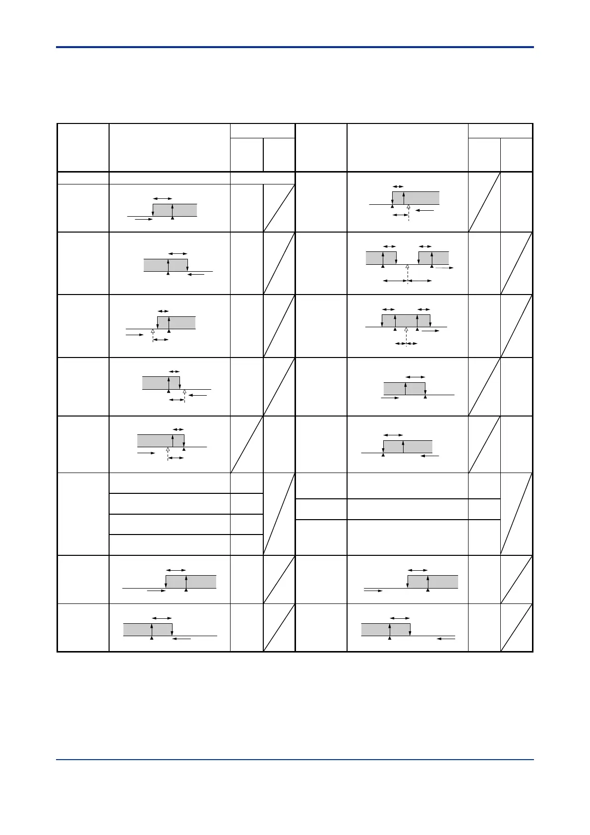
■ List of Alarm Types
The table below shows the alarm types and alarm actions.
In the table, codes 1 to 10 are not provided with stand-by actions, while codes 11 to 20 are
provided with stand-by actions.
Alarm action
Alarm action
Alarm type codeAlarm type code
Alarm type
“Open/close” shows status of relay contact,
and “lit” and “unlit” shows status of lamp
Contact
closes
if alarm
occurs
Contact
opens
if alarm
occurs
Contact
closes
if alarm
occurs
Contact
opens
if alarm
occurs
Alarm type
No alarm OFF
PV high limit
PV low limit
Alarm setpoint
Closed (lit)
Hysteresis
PV
Open (unlit)
1
11
De-energized
on deviation low
limit alarm
Deviation
setpoint
Target SP
Open (lit)
Hysteresis
Closed
(unlit)
6
16
Closed (lit)
Hysteresis
Open (unlit)
Alarm setpoint PV
2
12
Deviation high
and low limits
Target SP
PV
Hysteresis Hysteresis
Deviation setpoint
Closed
(lit)
Open
(unlit)
Closed
(lit)
7
17
Deviation high
limit
Hysteresis
PV
Open (unlit)
Open (unlit)
Open (unlit)
Closed (lit)
Open (unlit)
Closed (lit)
Closed (lit)
Open (unlit)
Closed (lit)
Target SP
Deviation setpoint
Closed (lit)
3
13
Deviation
within
high and low
limits
Deviation setpoint
Target SP
PV
Hysteresis
Hysteresis
Open
(unlit)
Open
(unlit)
Closed
(lit)
8
18
Deviation low
limit
Target SP
Deviation setpoint
Open (unlit)
Hysteresis
Closed (lit)
4
14
De-energized on
PV high limit
De-energized on
PV low limit
PV
Open (lit)
Alarm setpoint
Hysteresis
Closed
(unlit)
9
19
De-energized on
deviation high
limit alarm
PV
Open (lit)
Target SP
Deviation
setpoint
Hysteresis
Closed
(unlit)
5
15
Alarm setpoint
Hysteresis
PV
Open (lit)
Closed
(unlit)
PV
PV
10
20
25
26
27
SP high
limit
SP low
limit
Alarm setpoint
Hysteresis
SP
28
21
22
23
24
Output high limit
Alarm setpointOutput value
Hysteresis
30
Hysteresis
Alarm setpoint
SP
29
Output low limit
Hysteresis
Alarm setpoint Output value
31
“Open/close” shows status of relay contact,
and “lit” and “unlit” shows status of lamp
Upward (hour/minute)
Sensor
grounding
alarm
Sensor grounding alarm
Downward (hour/minute)
Fault diagnosis
output (Note1)
Fault diagnosis output
Timer function
(Alarm-1 only)
Upward (minute/second)
FAIL output
(Note2)
The controller stops when in a FAIL state.
The control output is set to “OFF” or
“0%” and the alarm output is set to
“OFF”.
Downward (minute/second)
Note 1:The fault diagnosis output turns on in case of input burnout, A/D converter failure, or reference junction compensation
(RJC) failure. For input burnout or A/D converter failure, the control output is set to the setpoint of the Preset Output
Value operating parameter (PO).
Note 2:The FAIL output is on during normal operation and turns off in case of failure.

 Loading...


