JOHNSON CONTROLS
24
FORM 102.20-N1
ISSUE DATE: 7/06/2016
SECTION 3 - HANDLING, STORAGE, AND INSTALLATION
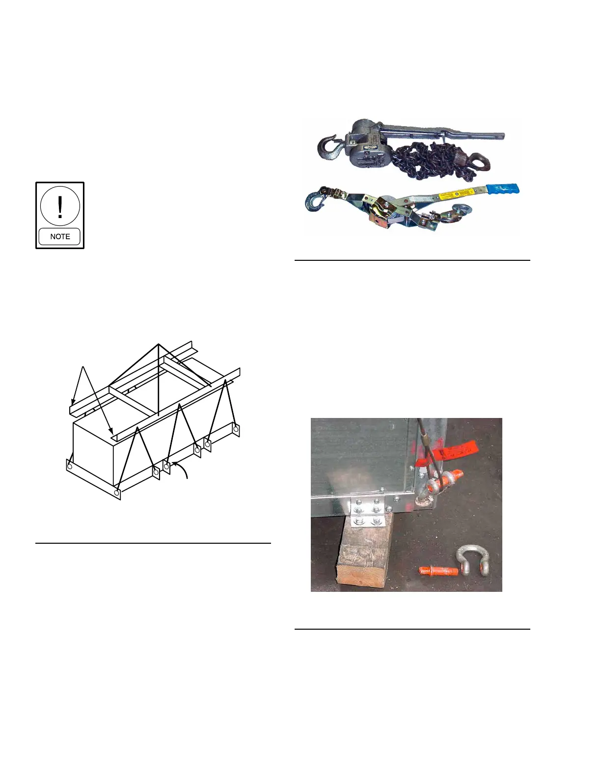
COME-A-LONGS (POWER PULLS)
If the AHU has multiple sections, use come-a-longs
(power pulls) as shown in Figure 11 on page 24 to
pull the sections or skids together.
LD09613a
FIGURE 11 - TYPICAL COME-A-LONGS
PROPER LIFTING WITH SHACKLES
Shackles are fastened to a sling or chain, which is used
to lift and lower the sections in a tiered AHU. Refer to
the following figures for proper lifting:
• Figure 12 on page 24 for proper lifting with a
hook and shackle at the corners.
• Figure 13 on page 25 for proper lifting with a
hook and shackle at the lifting lugs.
• Figure 14 on page 25 for lifting with a base rail.
LD13767
FIGURE 12 - PROPER LIFTING WITH SHACKLE
WITH CORNER CONNECTOR CORNERS
An experienced and reliable rigger must handle the un-
loading and final placement of the AHU, and must be
advised of the following:
• AHU contains internal components and should be
handled in an upright position.
• Care must be exercised to avoid twisting the
equipment structure.
• Prevent unnecessary jarring or rough handling.
Proper rigging and handling of the
equipment is mandatory during unload-
ing and setting it into position to prevent
voiding the warranty.
Use the proper spreader bars and hoisting lines when
rigging to prevent damage to the AHU casing.
When lifting long AHUs, a special system must be
used to insure a minimum 60° angle between the lift-
ing lugs and spreader bar/frame.
FIGURE 10 - RECOMMENDED LIFTING WITH
MULTIPLE POINTS
USING FORK LIFT IN SPECIAL
CIRCUMSTANCES
Forklifts should not be used to off-load AHUs except
in special circumstances. If moving an AHU with a
fork lift or similar equipment becomes necessary, make
sure the lifting forks are long enough to reach from the
fork truck to the opposite side and slightly beyond the
AHU. Leave the shipping blocks attached to the bot-
tom of the AHU until it is moved to its final location.
There is no structural support under the equipment ex-
cept what is visible from the perimeter.
SPREADER
BARS
60° MIN
LD13765b