JOHNSON CONTROLS
51
SECTION 3 - HANDLING, STORAGE, AND INSTALLATION
FORM 102.20-N1
ISSUE DATE: 7/06/2016
3
FILLING INERTIA FAN BASE
Inertia fan bases are pre-engineered according to the
fan and motor size. Use the following instructions to
fill an inertia fan base with concrete.
• Calculate the amount of concrete by measuring
the overall length and width of the fan base as-
sembly cavities that have the corrugated metal
bottoms. The standard depth of a cavity is 4 in.
• Fill each cavity to the top with wet concrete. Do
not get concrete mix on the bolts and adjusting
parts of the adjustable motor base, sheaves, belts,
orontheoorundertheedgesoftheisolatedfan
base.
STEAM HUMIDIFIER
If purchased, steam humidifiers are provided with fac-
tory mounted dispersion equipment inside the AHU.
The steam injection or generating equipment, meter-
ing devices, and sundries are shipped loose with the
AHU. Humidifier manufacturer’s installation, opera-
tion and maintenance information is packaged with the
humidifier. The installing contractor(s) is responsible
for supplying all required steam supply and condensate
piping, and wiring.
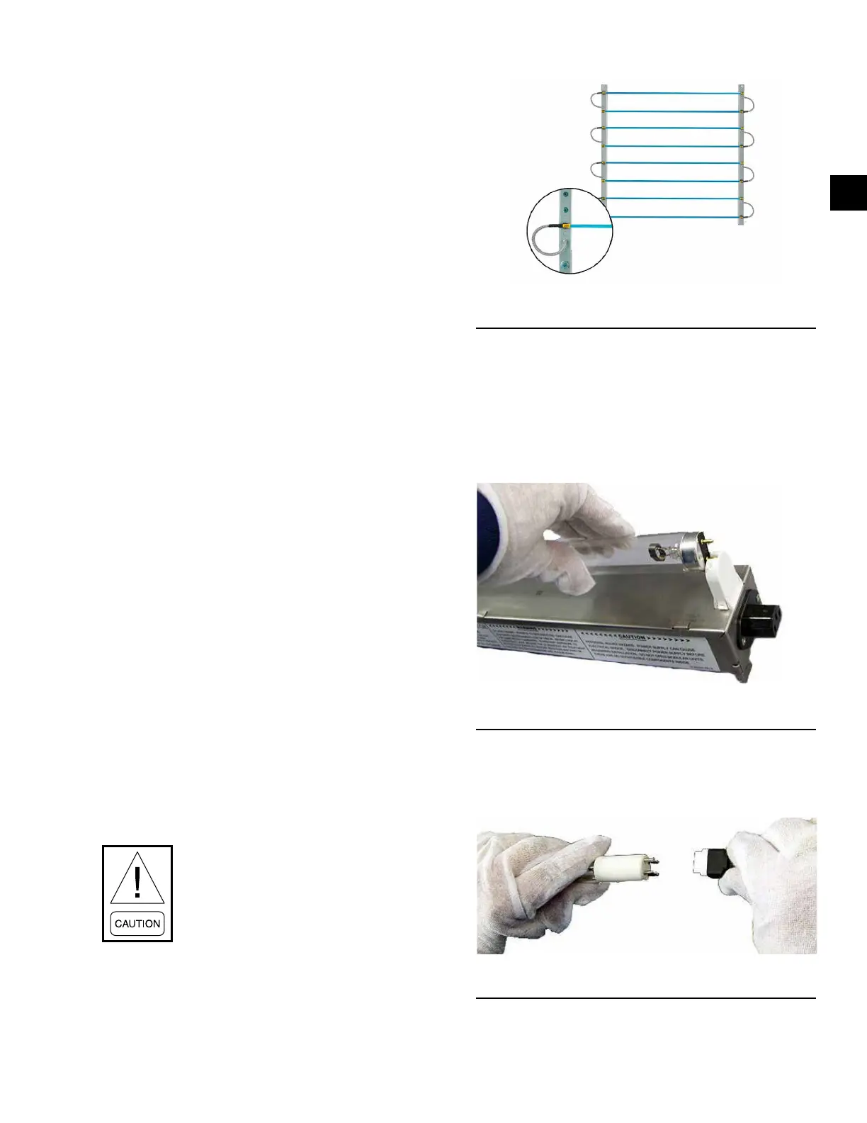
UVC EMITTER LAMPS
If purchased, the contractor is responsible for install-
ing the UV lamps, and connecting a 120 volt power
supply as shown in Figure 77 on page 51. The John-
son Controls factory provides the following pre-wired
parts.
• Internal wiring with a magnetic door safety switch
• A lockable disconnect switch with a Press to Test
pilot light
• A latching circuit that has to be manually re-ener-
gized on the AHU's exterior after a door has been
opened and closed.
Use clean cotton rags, clean jersey or
latex gloves to handle the lamps. DO
NOT touch UV lamps with bare hands or
leather gloves because the oil will damage
the lamps.
FIGURE 77 - V-MAX GRID LAMPS
V_Max
Two Types of Lamps
Three different types of UV lamps are used in AHUs:
V-Mod and V-Max Grid.
V-Mod Lamps - Install the two-pronged lamps into
the slotted fixtures as shown in Figure 78 on page
51, then rotate the lamp 90°.
FIGURE 78 - INSTALLING V-MOD LAMP
LD16551
V-Max Grid Lamps - Fit the four-pronged lamp into
the clamp mounted on the UV segment where a pigtail
is installed. Insert the prongs into the pigtail plug.
FIGURE 79 - INSTALLING V-MAX GRID LAMPS
LD16552