JOHNSON CONTROLS
99
SECTION 3 - HANDLING, STORAGE, AND INSTALLATION
FORM 102.20-N1
ISSUE DATE: 7/06/2016
3
4. Install the other three latches into the corners.
5. Rotate all of the latches outward, and insert the
lterintotheframe.
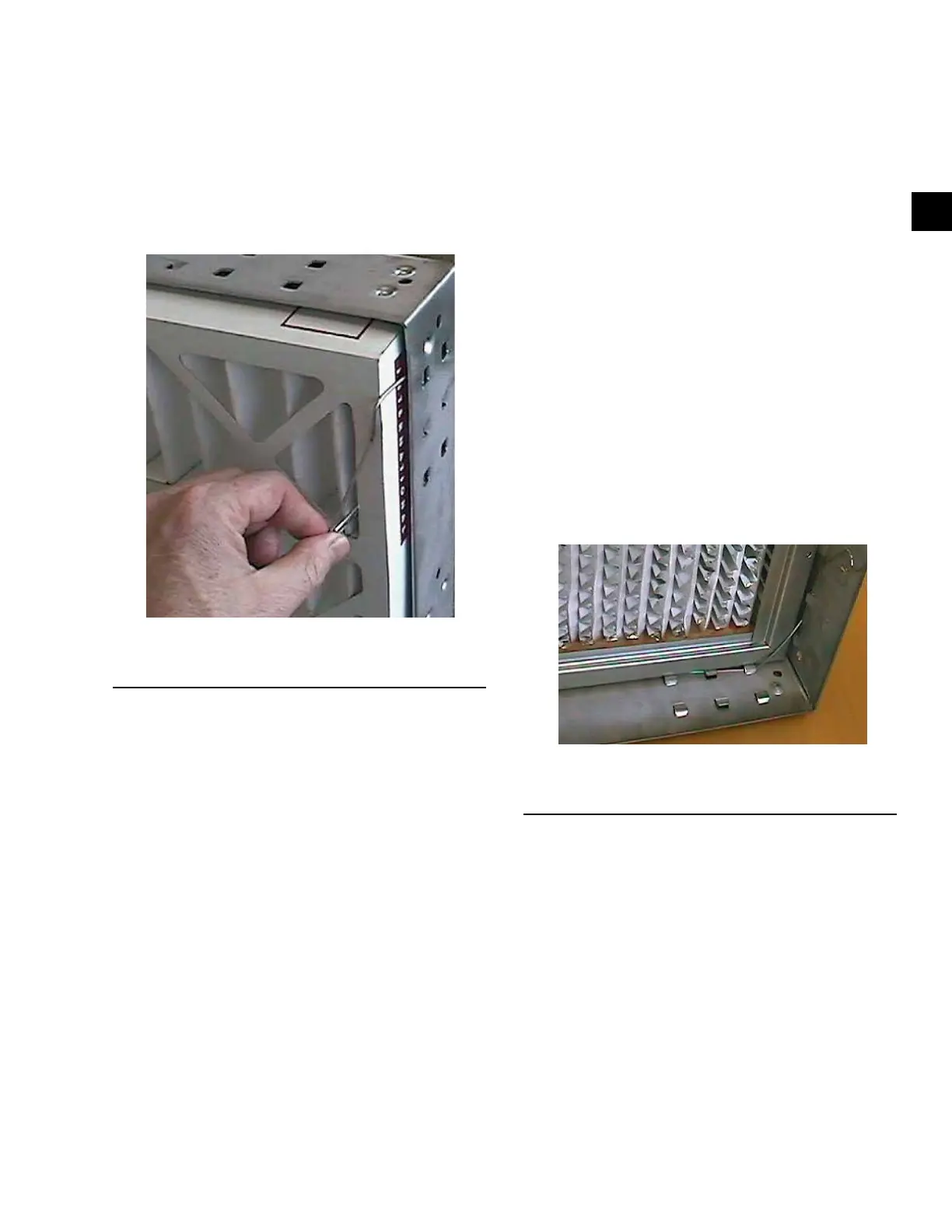
6. Grasp the loose end of the latch, and place it over
thelterframesothatthelatchsecuresthelter
into the frame as shown in Figure 151 on page
99.
FIGURE 151 - PLACE THE END OF THE LATCH
OVER THE FILTER FRAME
LD10179
7. Repeat the process with the remaining latches..
8. The lter should now be securely installed into
the frame.
Installing a Single Headered (SH) Filter
Use the following instructions to install a 2 in. Single
Headered (SH) filter into a 16 g galvanized hold-
ing frame with four latches (P/N 026-24788-702), as
shown in Figure 147 on page 95.
1. Install one latch at each corner (4 corners) of the
frame.Thelatchtsintotworowsofthreeknock-
outs. Use the row of knockouts closest to the gas-
ketfornominal1in.ltersorlterswitha13/16
in. single header. Use the second set of knockouts
fornominal2in.lters
2. Insert the straight end of the latch between the two
knockouts furthest from the corner.
3. Using a moderate amount of pressure, force the
latch over the third knockout. The latch should
now be trapped within the three knockouts, but
should be able to freely rotate.
4. The latch installation should be complete.
5. Rotatethelatchesoutward,andinserttheSHlter
intotheframe.Insertthebulkofthelterthrough
the frame, protruding out the backside. Only the
headeroftheltershouldbecontactingtheange
of the frame.
6. Afterthelterisplacedintotheframe,graspthe
circular end of the latch and rotate it across the
cornerofthelter.
7. Pushtheendofthelatchtowardsthelter,until
the latch catches beneath the frame knockout.
8. Repeat the process with the remaining latches.
9. The lter should now be securely installed into
the frame as shown in as shown in Figure 152 on
page 99.
FIGURE 152 - CORRECTLY INSTALLED
CARTRIDGE FILTER
LD10148
Installing a 2 in. Pre-Filter Combined with a
SH Final Filter
Use the following instructions to install a 2 in. pre-
filter combined with a SH final filter (Multi-Cell FM
Single Header or Multi-Sak) into a 16 g galvanized
holding frame with four latches (P/N 026-35778-604),
as shown in Figure 147 on page 95.
1. Follow the instructions for the SH lters on the
previous page, and then proceed with the follow-
inginstructionsfor2in.pre-lters.
2. Insert the straight end of the latch between the two
knockouts furthest from the corner.