JOHNSON CONTROLS
68
FORM 102.20-N1
ISSUE DATE: 7/06/2016
SECTION 3 - HANDLING, STORAGE, AND INSTALLATION
WIRING THE ELECTRIC HEAT DEVICE
It's the installer's responsibility to wire this device, if
the single point power was not purchased.
Power Options
The available power options are listed below:
• 460V-3PH
• 208/230V-3PH
• 380V-3PH
• 575V-3PH
Disconnect Switch Options
The available disconnect switch options are fused and
non-fused.
Knockouts are provided on the top and bottom of the
enclosure for field penetrations. Drill the foam panel
to utilize these knockout locations. Seal the penetra-
tions to prevent airflow or leakage. Refer to the service
manual for more information.
Use the following instructions to connect the discon-
nect switch:
1. Hook up the power, as shown in Figure 106 on
page 68. Terminals (shown) are for a 2-stage 24
VAC control interface, and may require a 120VAC
control interface, based upon the options selected.
Refer to the wiring diagram on the inside cover of
the electric heat control panel for more informa-
tion.
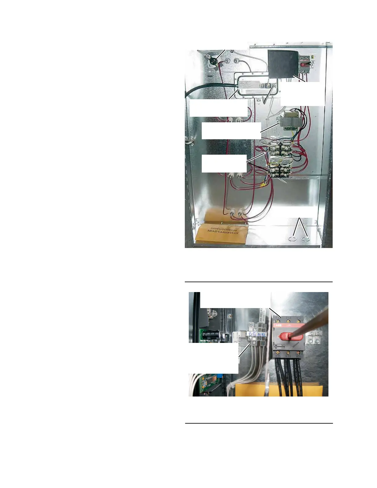
FIGURE 106 - TYPICAL ELECTRICAL HEAT
CONTROL PANEL INTERIOR WIRING AND
COMPONENTS
LD115934a
HIGH TEMPERATURE
CUTOUT
AIRFLOW PROVING
SWITCH
STAGING
CONTACTORS
CONTROL VOLTAGE
TRANSFORMER
MAIN
DISCONNECT
SWITCH
KNOCKOUTS
FIGURE 107 - TYPICAL FIELD AND POWER
CONNECTIONS
LD11595
FIELD CONTROL
WIRING AND
INTERFACE
TERMINALS
MAIN
DISCONNECT SWITCH