JOHNSON CONTROLS
88
FORM 102.20-N1
ISSUE DATE: 7/06/2016
SECTION 3 - HANDLING, STORAGE, AND INSTALLATION
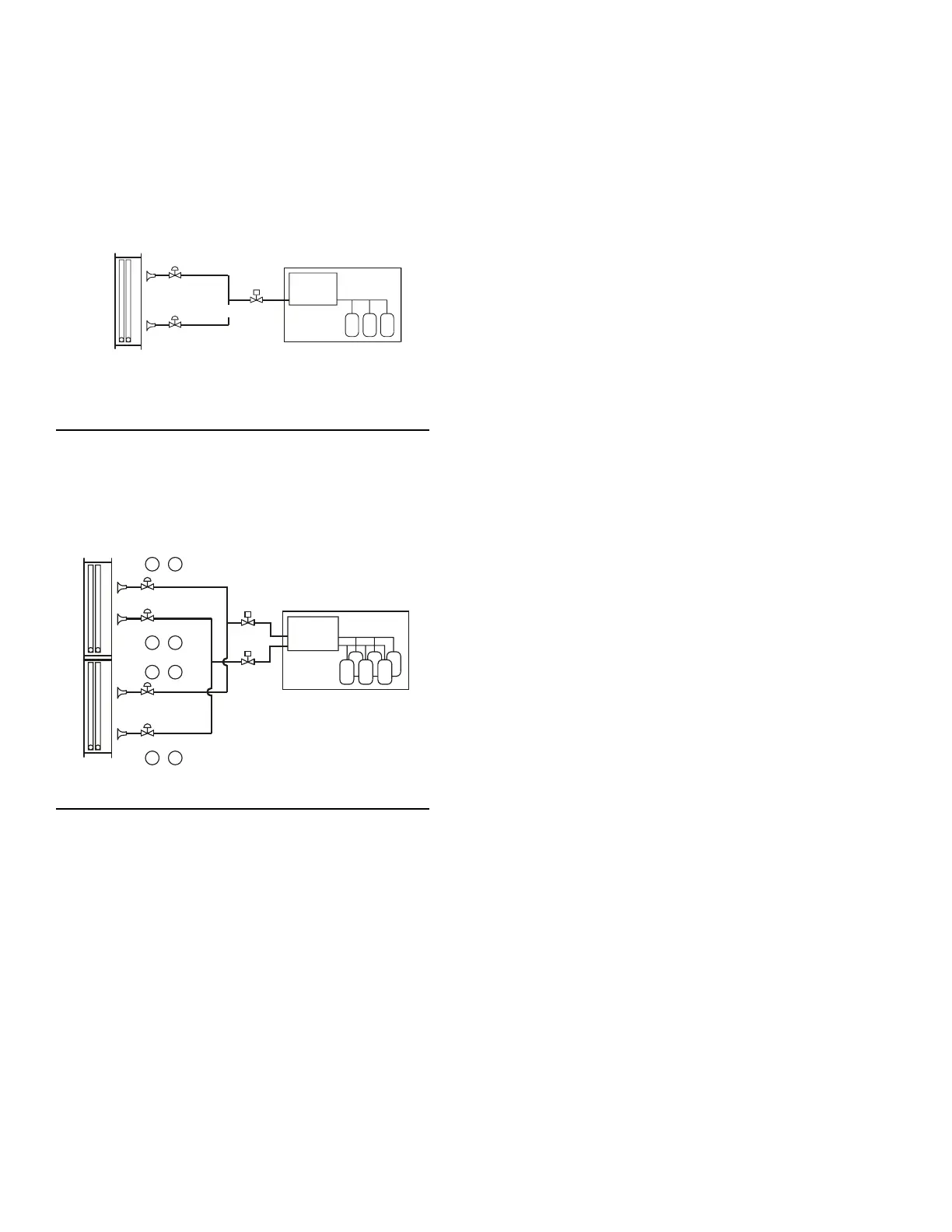
When the condensing AHU has three compressors per
circuit, use two coil circuits for each refrigerant circuit
as shown in Figure 136 on page 88. Each coil circuit
must have a dedicated TXV and distributor to handle
one coil circuit, and the LLSV should be sized to han-
dle the full capacity of the refrigerant circuit. Connect
the HGPB line to all distributors in the coil circuit.
FIGURE 136 - THREE COMPRESSOR UNIT
LD09151
Compressor #1
TXV
Compressor #3
Feeds Both Circuits
TXV
Compressor #2
LLSV
Condensing Unit
In a stacked coil with four coil circuits piped to a con-
denser with six compressors, the coil circuits would be
face split and interlaced with two interlaced circuits on
the lower coil section and two on the upper section as
shown in Figure 137 on page 88.
1-3
4-6
4-6
1-3
FIGURE 137 - SIX COMPRESSOR UNIT
LD09153
Comp
TXV1
TXV3
TXV2
TXV4
Comp
Comp
Comp
DX Coils
LLSV1
LLSV2
Condensing Unit
When sizing TXVs, size the TXV for the refrigerant
circuit tonnage divided by the number of DX coil liq-
uid distributors, which should be equal to or smaller
than the calculated value.
The first three compressors would be tied into LLSV1,
TXV1 and TXV2, which would provide full face con-
trol of the coil at the lowest cooling loads. Both dis-
tributors on each coil circuit would include auxiliary
side connectors for HGBP.
The second set of three compressors would be tied into
LLSV2, TXV3 and TXV4 to maintain full-face control
at higher loads. Refer to Guidelines for Proper Appli-
cation Piping and Guidelines for Split Systems (Form
050.40-ES3) for compressor staging solutions.
Advantages of Multiple Control Stages
The more control stages used, the more precise the con-
trol of the air temperature will be. Smaller incremental
changes in capacity will result in a more consistent DX
coil leaving air temperature, which will eliminate tem-
perature swings in the conditioned space and improve
the comfort level. But more importantly, a consistent
space temperature is crucial to many process applica-
tions.
The smaller changes in capacity that result from us-
ing a greater number of control stages will also extend
equipment life. The most important thing to remember
is to maintain full-face control of the coil at all cooling
loads. When row split coils are used, make sure that
the first LLSV is energized with the last coil circuit in
the leaving air stream, which is always the last one de-
energized too.
MAINTAINING ADEQUATE AIRFLOW
An electrical interlock between the AHU and the con-
denser must be included for permissive run of the
condenser. In addition, a differential pressure switch
mounted across the supply fan must always be includ-
ed to ensure airflow across the coil before the condens-
ing AHU is energized. The condenser must never be
operated unless the AHU fan is operating and air is
flowing across the active coil. Insufficient airflow will
result in liquid refrigerant returning to the condensing
AHU, which could damage the compressors by liquid
slugging or washing oil from the bearing surfaces.
In variable volume systems, the minimum acceptable
airflow for fixed speed or variable air volume (VAV)
systems is 350 FPM face velocity across each DX coil,
as applied to split DX systems. Make sure that the TXV
does not overfeed, because it could cause compressor
failure.
The air velocity flowing through chilled water and di-
rect expansion coils must not exceed specific recom-
mended values to prevent water carryover.