JOHNSON CONTROLS
48
FORM 102.20-N1
ISSUE DATE: 7/06/2016
SECTION 3 - HANDLING, STORAGE, AND INSTALLATION
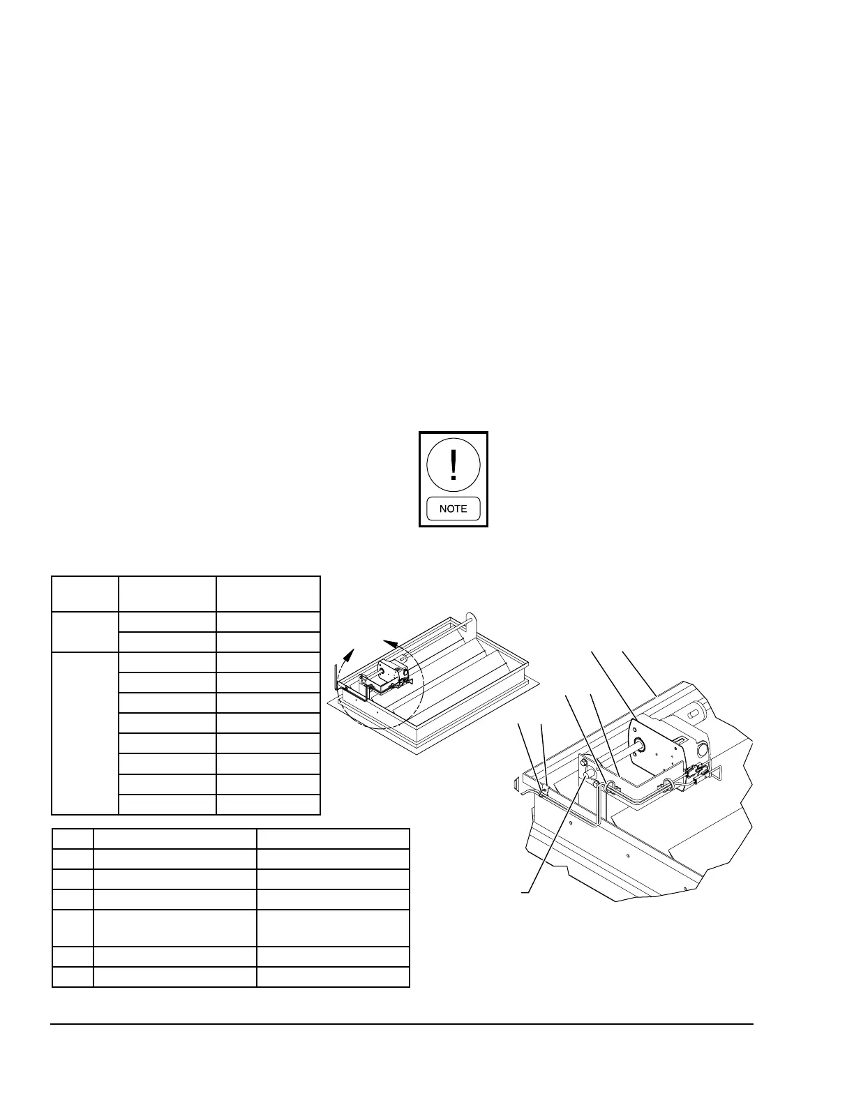
Installing Damper Actuator
Use the following instructions to install the actuator as
shown in Figure 72 on page 48.
Damper Blade Orientation
**Return air and mixing dampers:
Position blades so that they will be open once the actu-
ator is installed. This will be the dampers spring return
position. Note whether the damper shaft is rotated fully
clockwise or counter clockwise.
**Outside air and exhaust air dampers:
Position the damper blades so that they will be closed
once the actuator is installed. This will be the dampers
spring return position. Note whether the damper shaft
is rotated fully clock-wise or counter clockwise.
Actuator Installation
1. Remove the bearing plate from the damper frame
and jackshaft.
2. Slide the damper actuator onto the open end of
this shaft making sure that the proper spring re-
turn position on the face of the actuator matches
the damper shafts rotation, if not then reinstall the
actuatorwithitippedover.
3. Reinstall the bearing plate to the damper frame
and jackshaft.
4. Slide the damper actuator, mounting bracket into
the actuator mounting grooves and fasten to the
damper frame using self drilling screws.
5. Securely tighten the actuator shaft clamp to the
dampers jackshaft. Make sure at this point the
damper shaft is completely rotated to its proper
position.
6. Manually operate the actuator to its fully actuated
position using the crank arm provided with the ac-
tuator then release the spring to allow the damper
to go back to its original position. This will verify
the actuators spring rotation and stroke.
7. Set the damper actuators rotation selector switch
to the proper rotation required to actuate the
damper.
This will always be opposite the spring
return rotation.
LD17268
FIGURE 72 - INSTALLING THE DIRECT COUPLED ACTUATOR
$
6+$)7
ITEM DESCRIPTION YORK PART NUMBER
1 Damper See Spec Sht for P/N
2 Actuator See Spec Sht for P/N
3 Actuator Mounting Bracket See Table
4
7.8" length, 0.25" hole,
black 6.6 nylon
025-40605-001
5 Edge Clip # MCMS12-P-C 025-39067-002
6 Cable Tie 7.9: LG 025-39031-002
VENDOR
YORK PART
NUMBER
BRACKET
PART NUMBER
Belimo
025-25737-001 086-00138-014
025-25737-002 086-00138-014
JCI
025-39114-001 086-00138-013
025-39114-002 086-00138-013
025-39115-001 086-00138-016
025-39115-002 086-00138-016
025-39116-001 086-00138-014
025-39116-002 086-00138-014
025-39117-001 086-00138-014
025-39117-002 086-00138-014