JOHNSON CONTROLS
72
FORM 102.20-N1
ISSUE DATE: 7/06/2016
SECTION 3 - HANDLING, STORAGE, AND INSTALLATION
10. If the heater is wired to a heating/cooling thermo-
stat, use a thermostat with isolating circuits to pre-
vent possible interconnection of Class 2 outputs.
11. If the heating elements are divided into several
sections with resistance wire between two or more
sections, calculate the maximum kW per sq. ft as
follows:
Number of heated
sections x area of
one heated section
Heater nameplate KW
ELECTRIC HUMIDIFIER
It's the installer's responsibility to wire this device be-
cause this device is not included in the single point
power option.
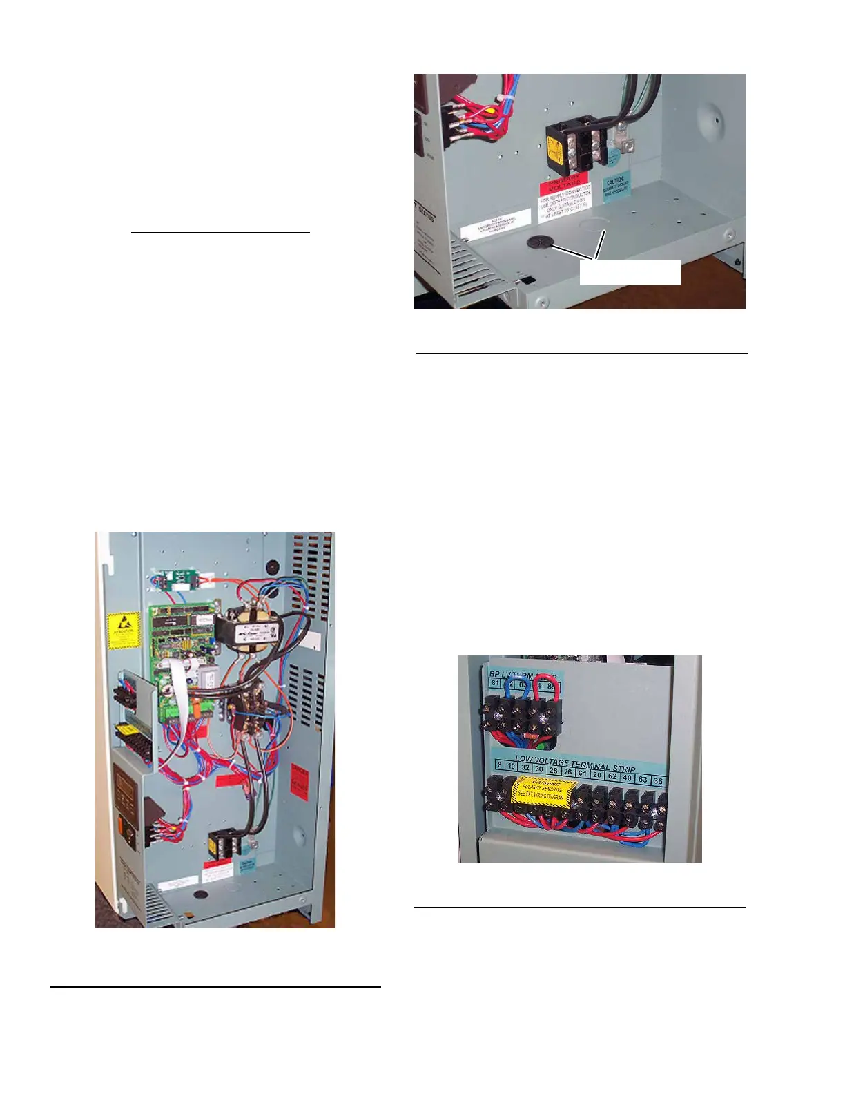
Figure 110 on page 72 represents a typical electric
humidifier panel layout. The supply power knockout is
located in the bottom of the electrical panel as shown
in Figure 111 on page 72. All conduits beginning or
ending on the inside of the pressurized or conditioned
areas (i.e. AHU) must have the conduit openings sealed
to prevent air from passing through it.
FIGURE 110 - LAYOUT OF TYPICAL HUMIDIFIER
PANEL
LD11726
FIGURE 111 - SUPPLY POWER KNOCKOUTS
LD11727
KNOCKOUTS
All AHU penetrations must be sealed to prevent air and
water leakage. Refer to Field Penetrations for Piping
and Electrical Connections on page 63.
Field provided disconnects must provide circuit pro-
tection according to the humidifier nameplate. All field
wiring to the humidifier must be in accordance with
NEC and local codes.
HUMIDIFIER
Control wiring diagrams are located in the humidi-
fier manufacturer's operator's manual, which can be
found inside the control panel or it is attached. Factory
package control drawings may not include humidifier
points as shown in Figure 112 on page 72.
FIGURE 112 - HUMIDIFIER POINTS
LD11725
If the humidifier operator's manual cannot be located
inside the humidifier, call Johnson Controls Airside
Product Technical Support to get a copy of the elec-
tronic version.