JOHNSON CONTROLS
37
SECTION 3 - HANDLING, STORAGE, AND INSTALLATION
FORM 102.20-N1
ISSUE DATE: 7/06/2016
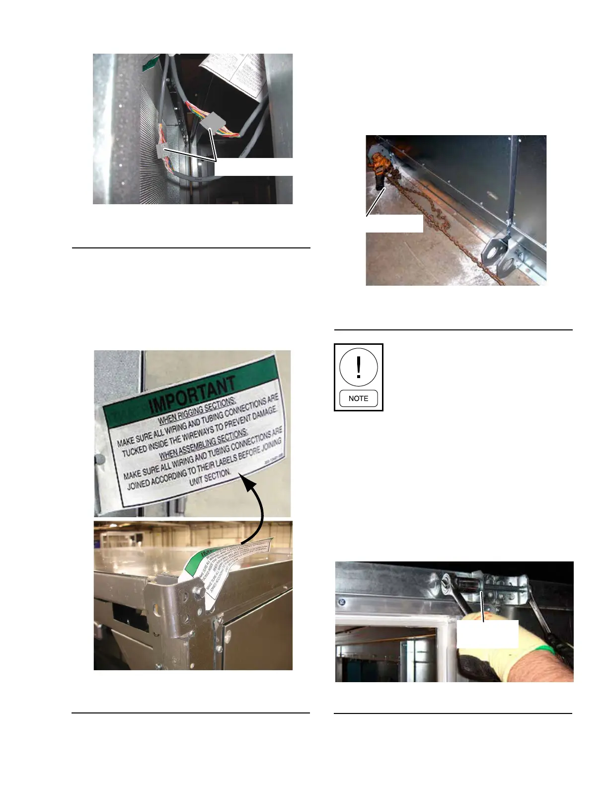
CONNECTORS
FIGURE 46 - ELECTRICAL CONNECTORS
(CONNECTED)
LD13374
8. After making the electrical and control connec-
tions and before proceeding with assembly, re-
move and reposition the top shipping split angle
as shown in Figure 47 on page 37.
Pulling the Solution XT Sections Together
Use the following instructions to pull the sections to-
gether.
1. Attach the come-a-longs to the far end of the next
section as shown in Figure 48 on page 37.
FIGURE 48 - COME-A-LONG ATTACHED TO A
SECTION
LD13775
COME-A-LONG
Make sure the chain does not apply pres-
sure to the drain connection. Improper
positioning of the chain may cause dam-
age to the AHU.
2. Start pulling the sections together evenly on both
sides.
a. Make sure all electrical or control wires or
tubes are clear.
b. Guide the top raceways together by plac-
ing the rods or drift pins through the holes
in the top guide angles. When the raceways
are together, install the long bolts provided as
shown in Figure 49 on page 37.
FIGURE 49 - BRING SHIPPING SPLITS TOGETHER
LD13775
SHIPPING-
SPLIT
FIGURE 47 - REMOVE AND REPOSITION
SHIPPING SPLIT ANGLE
LD14097