JOHNSON CONTROLS
29
SECTION 3 - HANDLING, STORAGE, AND INSTALLATION
FORM 102.20-N1
ISSUE DATE: 7/06/2016
3
Installing Ceiling Suspended AHUs
It is recommended that support is structur-
ally engineered to prevent exing, sagging
or twisting of the AHUs.
Use the following instructions to prepare the site for
ceiling suspended AHUs. Refer to Figure 20 on page
29 for proper support in the direction of airflow,
and/or if the AHU is positioned perpendicular to the
direction of the air flow.
Structure Positioned in Direction of Airow
The AHU base must be supported continuously on
both sides.
Structure Positioned Perpendicular to Airow
The AHUs must be supported (at a minimum) at the
following locations:
• Both ends
• At each shipping split, if applicable
• Upstream and downstream of each cooling coil
segment
• Under heavy components like fans, attenuators,
and heating segment.
• As a general rule, cross members should be placed
every 96 in., in addition to each shipping split.
DO NOT obstruct the door operation,
lter access, piping, electrical or control
connections with suspension members.
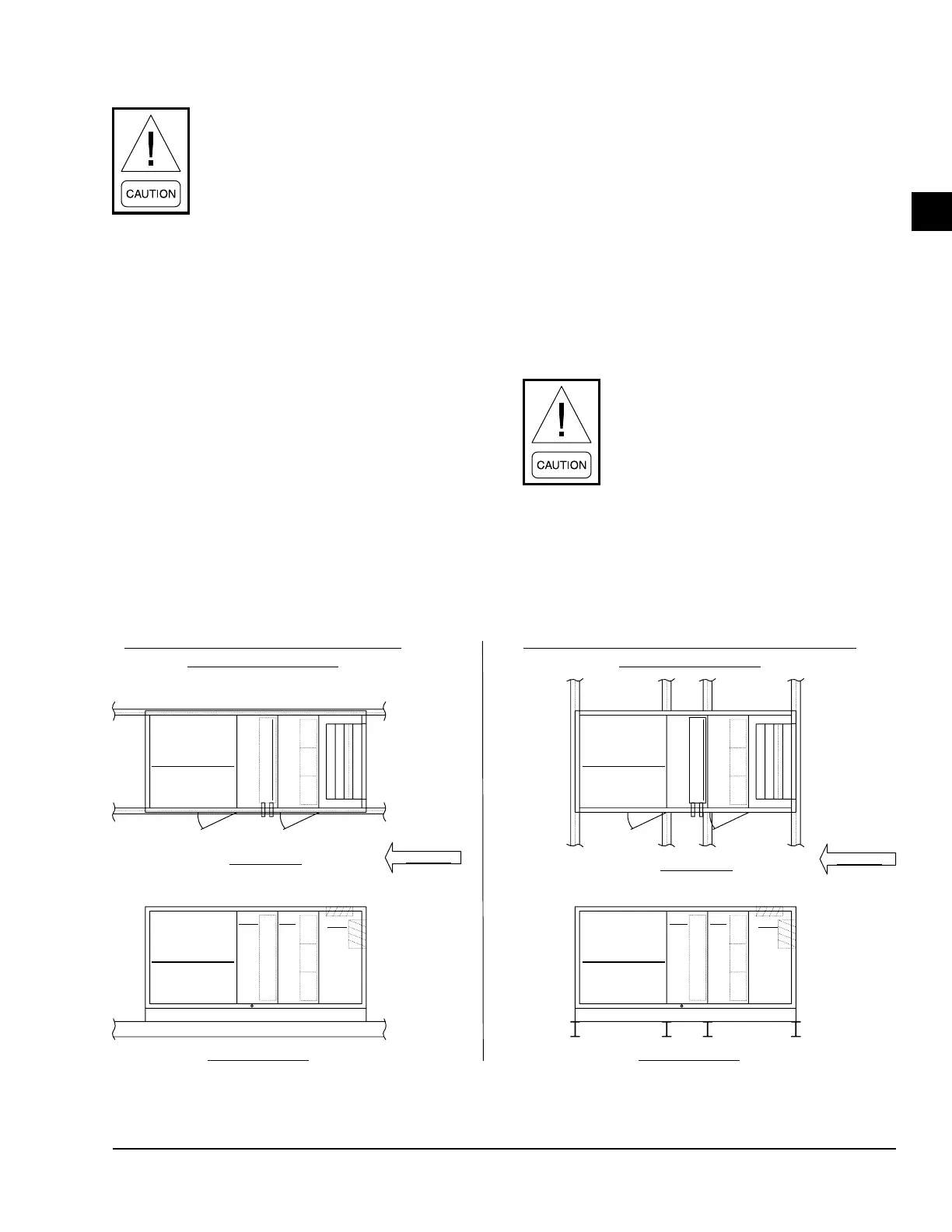
FIGURE 20 - CEILING SUSPENDED AHU ON STRUCTURAL STEEL
STRUCTURE PARALLEL TO AIRFLOW
(units under 60" wide)
STRUCTURE PERPENDICULAR TO AIRFLOW
(units over 60" wide)
Plain View
Plain View
Air Flow
Air Flow
Fan Section Fan Section
Fan Section Fan Section
Elevation View Elevation View
BDW COOLING
BDW COOLING
MC CCRF RF
MB MB