JOHNSON CONTROLS
50
FORM 102.20-N1
ISSUE DATE: 7/06/2016
SECTION 3 - HANDLING, STORAGE, AND INSTALLATION
Installing Field Supplied MZ Damper
Actuators
When the actuators are field supplied for MZ dampers,
use the following information to select the correct size
actuator.
• Required torque is 7 in-lb/sq. ft of damper area up
to 2500 feet per minute (FPM).
• Damper blades are 6 in. wide and vary in height.
• Calculate the torque by the number and size of
blades in each zone. There are hot deck blades di-
rectly connected to cold deck blades.
• Determine the number of blades per zone by the
system cubic ft per minute (CFM), and static pres-
sure requirements for each zone by the engineer’s
construction documents.
• Cut the blade linkage (at rods) connecting all
blades of each deck at the appropriate places to di-
vide the decks into correct size zones. These rods
are mounted externally on the assembly. Make
suretocutoutasectionoftheatconnectingrod,
which will prevent interference when the zones
modulate in opposite directions.
• One damper shaft extension kit (P/N 026-33715-
002), as shown in Figure 74 on page 50 is pro-
vided for each zone per the factory order form.
FIGURE 74 - DAMPER SHAFT EXTENSION KIT
(P/N 026-33715-002)
LD116504
• The contractor should supply the actuators and
mounting brackets. The part numbers are avail-
able upon request.
• On the rear mount (discharge through end of the
AHU), always mount the actuators on the top of
the upper deck.
• Do not allow the duct insulation to restrict the
damper blades or external linkage.
• Direct coupled actuators are recommended.
• Make duct connections at the zone dividers with-
out restricting the damper blade(s).
BACK DRAFT DAMPERS FOR DUAL FANS
AND FAN ARRAYS
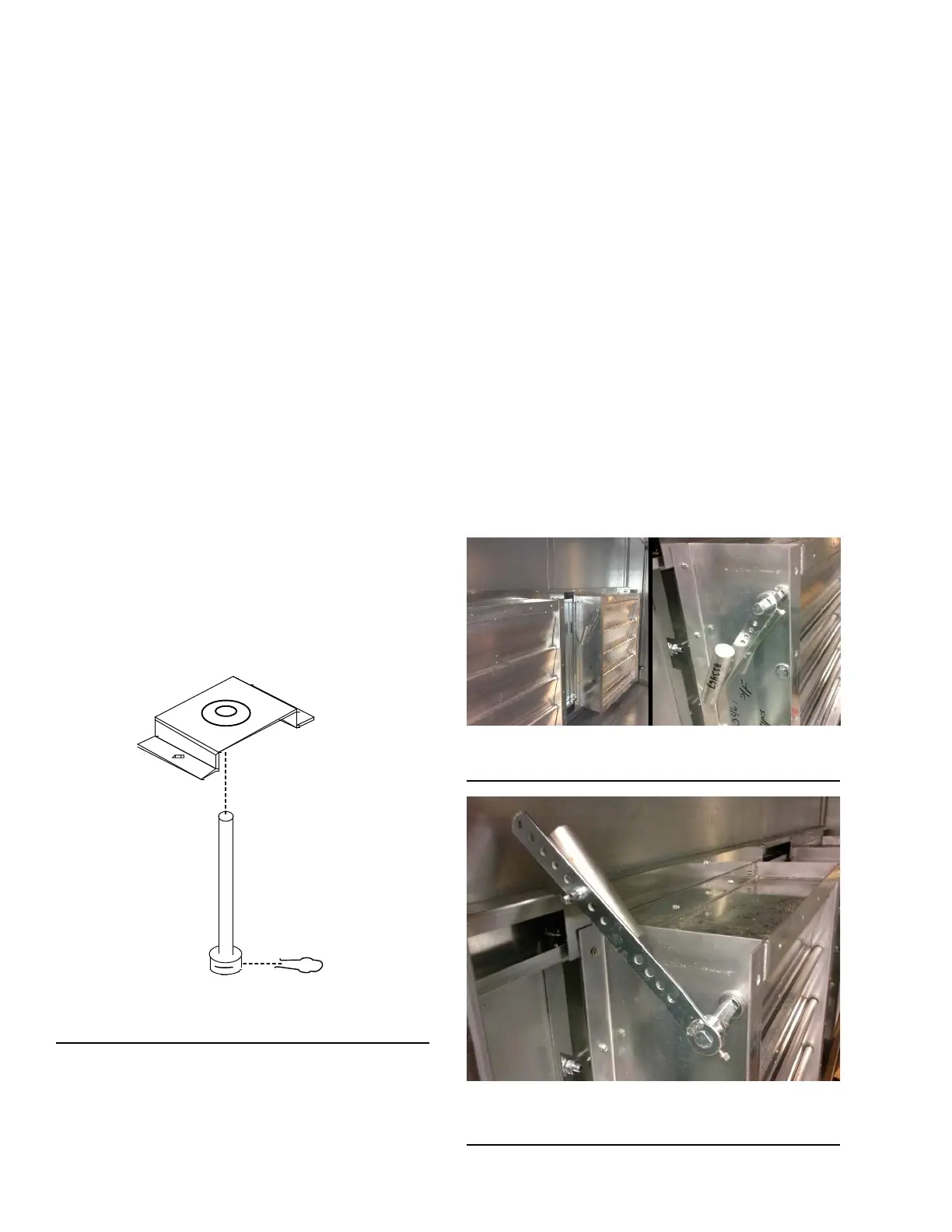
The counterbalance is locked into place for shipping
as shown in Figure 75 on page 50. Before startup,
the counterbalance will have to be released. To do this,
loosen the set screws and slide the counterbalance off
the end of the shaft. Flip the counterbalance and slide
it back on the shaft. Rotate the counterbalance above
the damper as shown in Figure 76 on page 50, and
then tighten the set screws. The counterbalance should
be free to rotate.
FIGURE 75 - COUNTERBALANCE LOCKED INTO
PLACE FOR SHIPPING
LD17103
FIGURE 76 - COUNTERBALANCE UNLOCKED FOR
START-UP
LD17198