EtherNet/IP Interface 5 - 9
5. The EA3600 is added to the I/O configuration and displays in the tree.
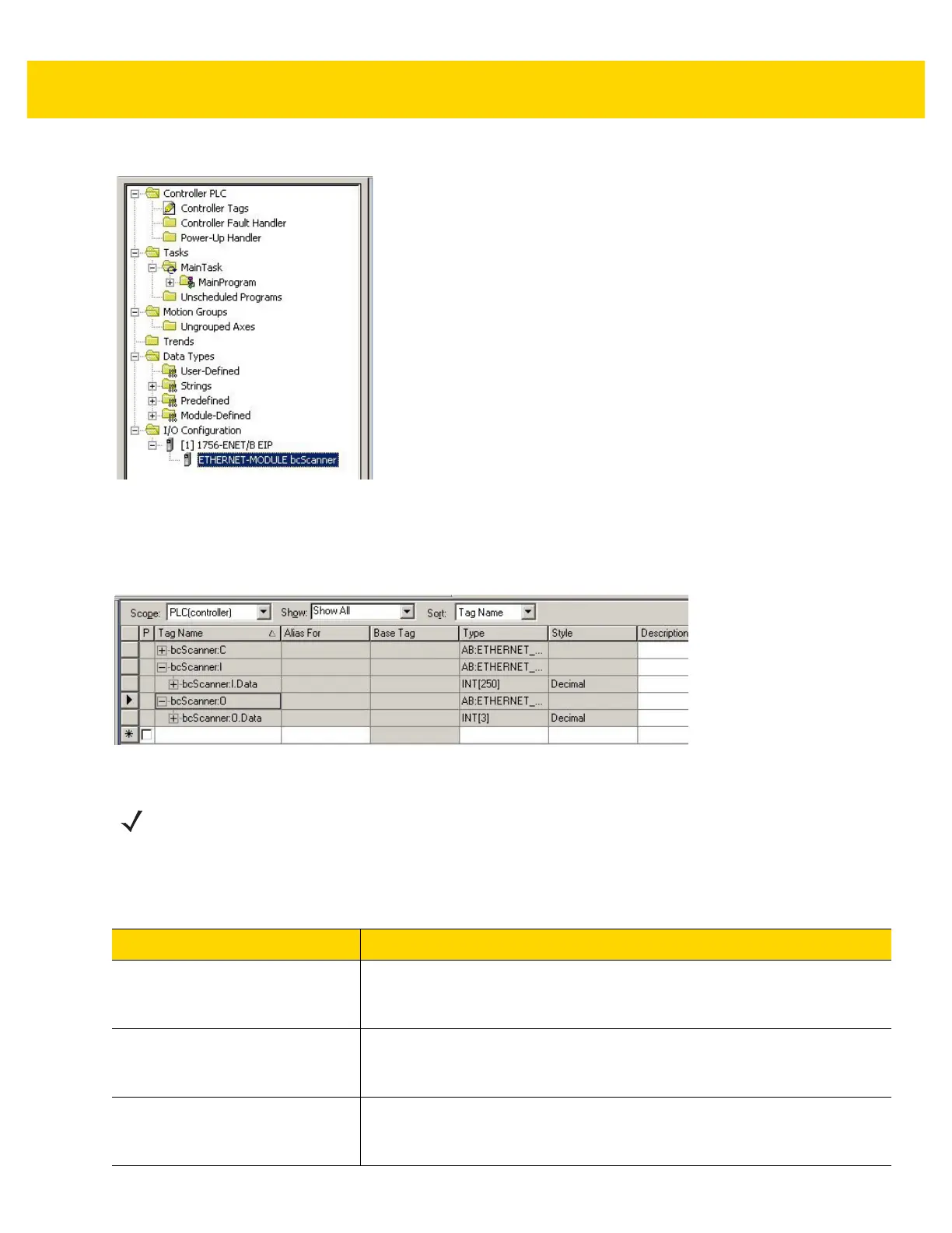
Figure 5-10 I/O Tree After EA3600 Add
EA3600 Tags
When the EA3600 is added to the I/O Configuration, a set of tags is created to allow the PLC logic to read and write
data to the EA3600 through the I/O connection. Figure 5-11 displays the tags that are created.
Figure 5-11 Tags Created with Generic Module
Table 5-2 refers to Figure 5-10.
NOTE The tag names are based on the name that was configured in the Module Properties dialog when the
EA3600 was added to the I/O Configuration. In the screen shot example the module was named
bcScanner.
Table 5-2 EA3600 Tags
Tag Name Type Description
scannerName:C Unused configuration data. When a generic Ethernet module is added to the
configuration, RSLogix automatically creates a configuration data buffer. In
the case of the EA3600, this buffer is not used.
scannerName:I.Data The Input data buffer holding data this is received from the EA3600. The
buffer is 248 words (496 bytes) long and is formatted as described in the
Status and Barcode Data section.
scannerName:O.Data The Output data buffer holding data that is sent to the EA3600. The buffer is 3
words (6 bytes) long and is formatted as described in the Barcode Transfer
Control Assembly section.