80 | 3DGence INDUSTRY F340
Notice: click save button after introducing any adjustments.
c) Print the offsets calibration model once again and visually inspect the printout:
• lack of rifts - the printing module calibrated properly
• occurrence of rifts between materials - necessity of another measurement with use of feeler gauge and calibration
of the printing module – point B
Example:
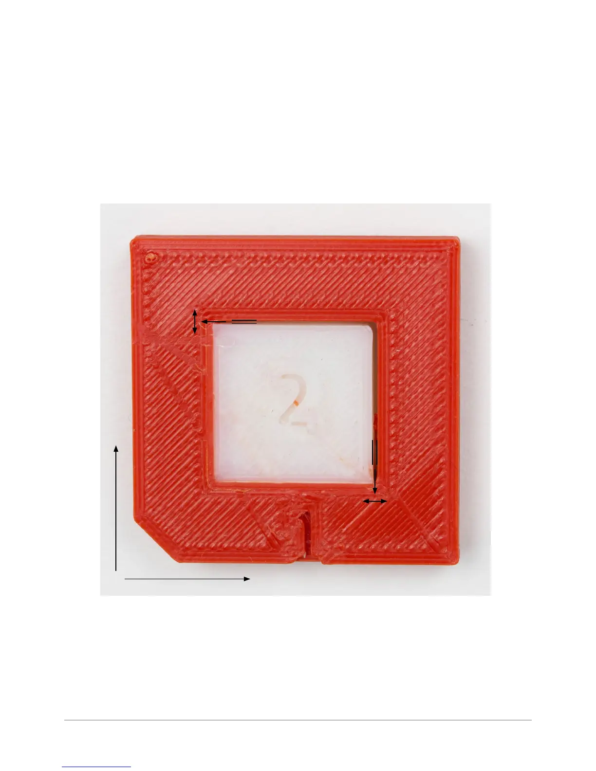
In order to verify XY offsets the DUAL-OFFSET-TEST.gcode was printed:
The width of rafts within both axes was measured on a printed model, the result: 0,6 mm in X axis and 0.4 mm in Y axis.
Complying to the axes turnaround, the user should set the offset to -0.6 mm for the X and -0.4 mm for the Y, then save
the adjustment.
Rys. 41. Exemplary offsets calibration.
0,4 mm
0,6 mm
Y
X