38 78-8130-6150-0-F
7. Continuealongthecablepath,re-insertingtheEarthContactFrameprobesevery
fewstepswhilewatchingthereceiverbargraph.Thebargraphonthereceiverwill
filltowardtherightsideofthedisplay(greenFault Finding Direction Indicator
[13](Seeillustrationbelow)),indicatingthatthefaultisaheadoftheoperator(in
thedirectionofthegreen-bandedlegoftheEarthContactFrame).
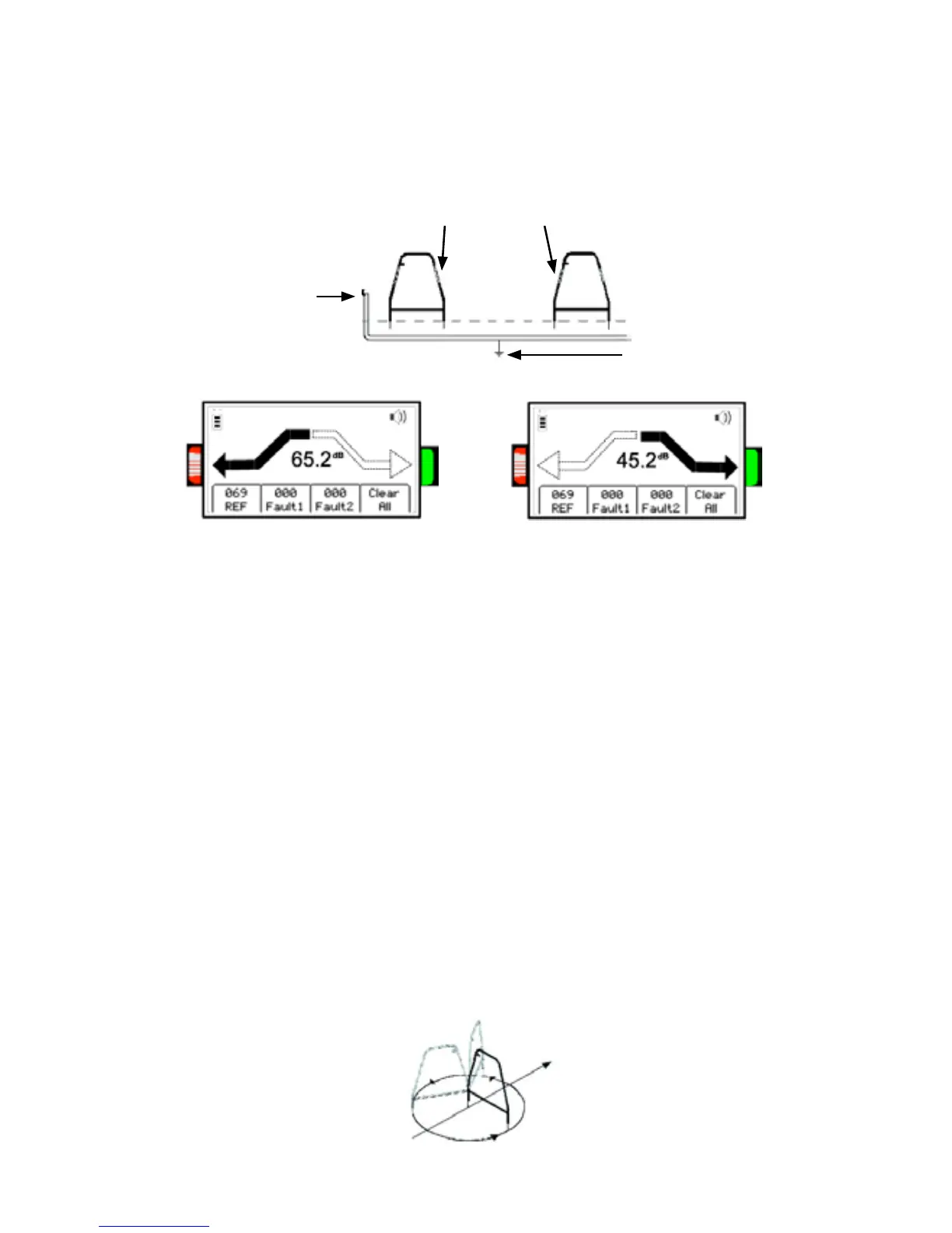
Transmitter Signal
Ground Fault location
Green Band Red-and-White-Striped Band
Move in direction of red-banded leg of
Earth Contact Frame.
Move in direction of green-banded leg of
Earth Contact Frame.
8. Whenthebargraphfillstowardtheleft(red-and-white-stripedFault Finding
Direction Indicator[13](Seeillustrationabove))sideofthedisplay,thefaulthas
beenpassedandisnowbehindtheoperator.Moveback,insertingtheEarthContact
Frameeveryfewinches,untilthearrowsalternatebacktogreen.Markthepoint
beneaththecenteroftheframe.TurntheEarthContactFrame90degreesandinsert
intothegroundoverthepreviouslymarkedpoint.MovetheEarthContactFrame
totheleftandright(followingthedirectionsofthegreenandredindicatorarrows).
Whenthearrowsreverseathirdtime,turntheEarthContactFrame90degrees
again.PinpointthefaultbymovingtheEarthContactFrameinthedirectionofthe
greenandredarrows.ThefaultislocatedbeneaththecenteroftheEarthContact
Framewhenthearrowschangefromonesidetotheotherthistime.
9. Toverifythefaultlocation,inserttheEarthContactFrame’sred-and-white-striped
probedirectlyonthespotidentifiedabove.PivottheEarthContactFrameina
circlearoundthered-and-white-stripedlegre-insertingthegreen-bandedleginthe
groundeveryfewdegreesofthecircle(Figure2).Thearrowshouldalwayspoint
towardtheleft(red)indicatingthatthefaultisdirectlybelowthered-and-white-
stripedleg.