78-8130-6150-0-F 55
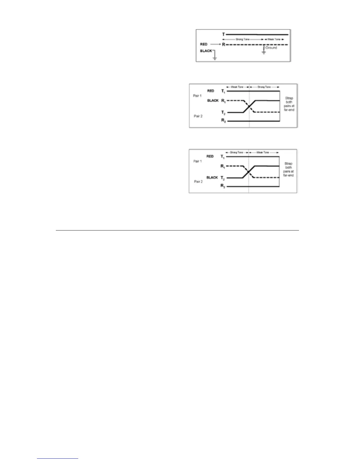
Ground: Redcliptothefaultedconductor;
Blackcliptoground.
Figure 3
Split:RedcliptoTipofPair1;Blackclipto
RingofPair1.
Figure 4
Verify Split: Redcliptogoodconductorof
Pair1;BlackcliptosplitconductorofPair2
Figure 5
B. Cable Identification
1. Transmitter Setup
1. Connectthe3M
™
Dynatel
™
Dyna-CouplertotheTransmitterOutput Jack[T-6]
usingthecouplercable.
Note: Cable Identification requires two Dyna-Couplers: one at the Transmitter and
one at the Receiver.
2. ClamptheDyna-Coupleraroundthecableorboththetipandringofapair.Make
sure the jaws fully close.
3. Pressandholdoff[T-1]toperformabatterycheck.
4. Presson: Ohm-meter/Fault Locate/Tone[T-2]threetimestosetthetransmitterto
Tonemode.
− TheindicatorflagwilllightintheDigitalDisplay[T-4]undertheToneicon.
5. PressOutput Level[T-5]forhighormaximumoutputpowerlevel.
− TheindicatorflagwilllightintheDigitalDisplay[T-4]abovetheOutputLevel
iconwheninhighoutputpowerlevelandflashwheninmaximumoutputpower
level.
− TheDigitalDisplay[T-4]willalternatelyflashbetween577and200K.
2. Receiver Setup
1. PressOn/Off (Power) [1]topowerthereceiveron.