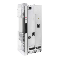
6. Twist the cable shields of the input cables into bundles and connect them and any
separate ground conductors or cables to the drive module ground terminal or to the
cabinet PE busbar.
7. Connect the phase conductors of the input cables to terminals L1/U1, L2/V1 and L3/W1
of the drive module. For the tightening torques, see the technical data.
Removing the control panel holder from the external control
unit
1. Disconnect the control panel cable from connector X13 on the control unit.
2. Loosen the mounting screws of the control panel holder and take the holder off.
Attaching the control cable clamp plate
Attach the control cable clamp plate either to the top or base of the control unit with four
screws as shown below.
Note: If you install the FSO-xx safety functions module above the control unit, attach the
control cable clamp plate on the base of the control unit.
106 Electrical installation

 Loading...