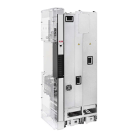
1.
Stop the drive and do the steps in section Electrical safety precautions (page 18) before
you start the work.
2. If the bottom plate of the FSO-xx module looks different from that in the drawing below,
remove the bottom plate and attach the alternative bottom plate from the FSO package
to module.
3. Connect the FSO-xx data cable to connector X12 on the control unit.
4. Attach the FSO-xx module to Slot 2 with four screws.
5. Tighten the FSO module electronics grounding screw to 0.8 N·m. Note: The screw
tightens the connections and grounds the module. It is essential for fulfilling the EMC
requirements and for proper operation of the module.
6. Connect the FSO-xx data cable to FSO-xx connector X110.
7. Connect the Safe torque off four-wire cable to connector X111 on the module and to
connector XSTO on the drive module control unit.
8. Connect the external +24 V power supply cable to connector X112.
9.
Connect the other wires as shown in FSO-12 safety functions module user’s manual
(3AXD50000015612 [English]) or FSO-21 safety functions module user’s manual
(3AXD50000015614 [English]).
Installation on the external control unit
■ Installing I/O extension, fieldbus adapter and pulse encoder interface
modules
See section Overview of power and control connections for the available slots for each
module.
Electrical installation 119

 Loading...