FDPI-02 diagnostics and panel interface installed onto the motor-side converter control unitX1-1
X2: Daisy chain bus terminal 1, RJ-45 shielded female connector for connecting a control panelX2-X204
X3: Daisy chain bus terminal 2, RJ-45 shielded female connector for connecting to the line-side
converter control unit RJ-45 connector (X13, CONTROL PANEL)
X3-2
Drive 23
Drive 34
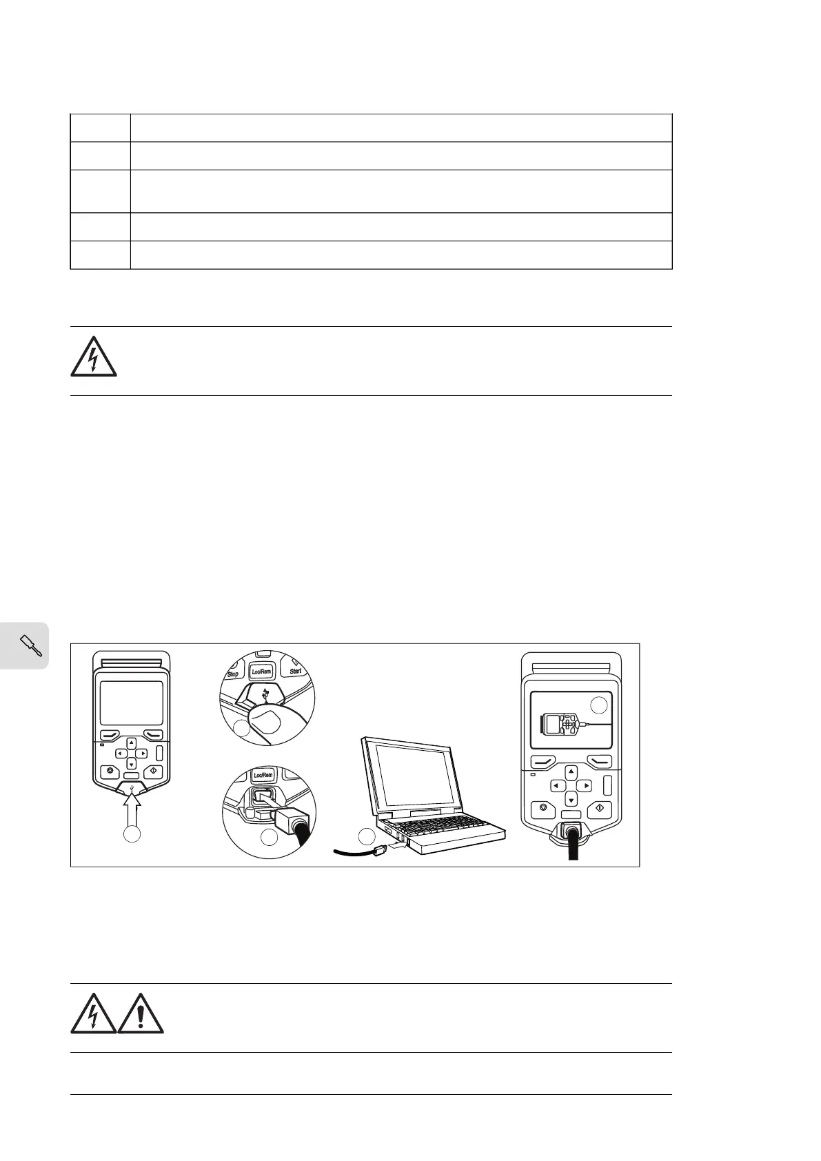
Connecting a PC
WARNING!
Do not connect the PC directly to the control panel connector of the control unit
as this can cause damage.
A PC (with eg, the Drive composer PC tool) can be connected as follows:
1. Connect an ACx-AP-x control panel to the unit either
• by inserting the control panel into the panel holder or platform, or
• by using an Ethernet (eg, Cat 5e) networking cable.
2. Remove the USB connector cover on the front of the control panel.
3. Connect an USB cable (Type A to Type Mini-B) between the USB connector on the
control panel (3a) and a free USB port on the PC (3b).
4. The panel will display an indication whenever the connection is active.
5. See the documentation of the PC tool for setup instructions.
?
Start
Stop
Loc/Rem
?
Start
Stop
Loc/Rem
USB connected
3a
4
3b
2
2
Installing option modules
■ Installing the FSO-xx safety functions module
Install the FSO safety functions module in Slot 2 of the control unit as described below.
WARNING!
Obey the safety instructions of the drive. If you ignore them, injury or death,
or damage to the equipment can occur.
118 Electrical installation

 Loading...


