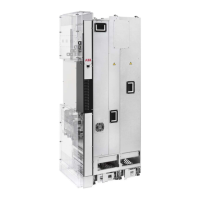
■ Block diagram of the main circuit of the drive module
T1/U2
T2/V2
T3/W2
7
3
54
6
L1/U1
L2/V1
L3/W1
UDC- UDC+
PE
1
2
8
A
ACS880-14 drive moduleA
Charging circuit contactor1
Charging circuit2
Line contactor3
LCL filter4
Line-side converter5
DC link. DC circuit between the line-side converter and motor-side converter.6
Motor-side converter7
Common mode filter (+E208)8
■ Line-side converter
The line-side converter rectifies three-phase AC current to direct current for the intermediate
DC link of the drive.
The line-side converter can transfer energy from the electrical power system to the drive
DC link and vice versa.Thus the drive can operate the motor in all four quadrants (speed,
torque). The figure below visualizes the operation of the four-quadrant drive. In quadrants
I and III, the drive operates in the motoring mode and takes energy from the power system.
In quadrants II and IV, the drive operates in generating mode, and regenerates energy back
to the power system.
32 Operation principle and hardware description

 Loading...